Fellows Corner
Protecting metallic structures from corrosive attack is not just about using coatings or cathodic protection, the design of the structure also plays an important part. There maybe situations which call for two different metals, or alloys, to be joined. If these metals are electrically connected under conditions permitting the formation of a “corrosion battery”, then in this situation, one metal can corrode preferentially in relation to the other metal to which it is physically and electrically connected. This is termed “galvanic corrosion”.
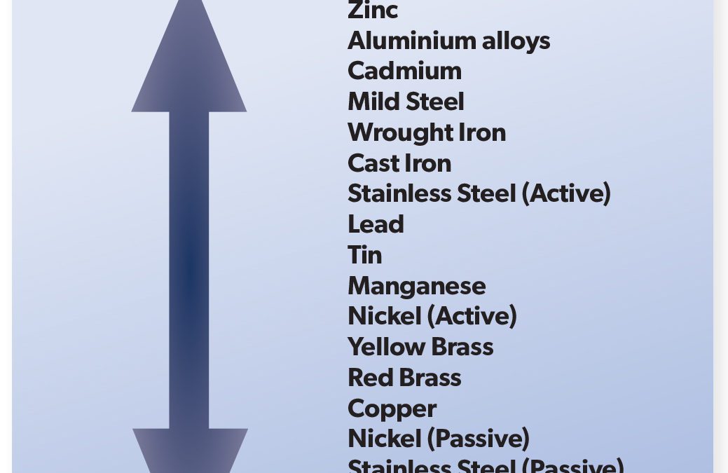
Galvanic corrosion is an extremely important corrosion process, and one that is frequently encountered. The principles of galvanic corrosion are used to advantage in the cathodic protection of surfaces by using sacrificial metal anodes or inorganic protective coatings. The Galvanic Series lists the activity of metals in order, from the most active (magnesium) to the least active (platinum). When two metals are connected, the metal located higher up the scale will corrode preferentially, and thereby protect the metal lower down the scale from corrosion attack. As an example, if copper and zinc are connected together, the zinc will dissolve, or be corroded preferentially, thus protecting the copper. The metal attacked is defined as the anode, thus the zinc will serve as an anodic area, and the copper will form the cathodic, or the protected area. The function of each will be identical to that found in the typical corrosion cell, as in the set up for rusting of iron. The intensity with which the two metals react in this preferential manner can be measured by the distance between the two metals in the Galvanic Scale. As magnesium is at the top of the scale it will have a tendency to corrode in preference to any other metal shown on the Galvanic Scale, conversely, platinum, which is extremely inert, never corrodes preferentially. While the tendency to corrode depends on the kinds of metal coupled together, the rate at which the corroding anode is attacked depends on the relative area of the anodes and cathodes joined together.
If a small magnesium anode is coupled to a large area of steel (as in protection of a ship’s hull), the anode area (being small as compared to the cathode area) will corrode very rapidly. This is due to the entire galvanic current being concentrated on a small area of active metal. Conversely, if the cathode area is small compared to the anode area the corrosion of the anode will be relatively slow, since the demand on the anode is spread evenly across the whole surface of the metal. It must be kept in mind that the areas of each metal involved are those in electrical contact and not just the areas of metal in physical contact. The area of metals in electrical contact will be determined by those areas which are in contact with an external conductive circuit (electrolyte).
For example, in the use of rivets of one metal to fasten together plates of different metal, we find an excellent example of possible effects of galvanic corrosion. If steel plates (anodes) were joined with copper rivets (cathodes) only a very slow corrosion of steel would occur, since the galvanic corrosive effect is spread out over a large area of steel. On the other hand, if copper plates (cathodes) were joined with steel rivets (anodes), a rapid rusting of the rivets would occur. The small area of rivets would be attacked by all the galvanic current generated by large copper plates and would corrode rapidly.
James McLaurin, Altrad Services

Fellows Corner
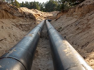
Buried metallic structures are common in the oil and gas, petrochemical, and chemical industries. These structures are exposed to a corrosive underground environment which results in their degradation and eventual failure in the form of loss of primary containment. The preferred fabrication materials for the construction of buried assets are carbon and low-alloy steels. Carbon and low alloy steels with some means of mitigation have low capital and operating cost (Opex and Capex) over the asset life cycle when compared to other engineering materials (e.g., polymeric and corrosion resistant alloys). Other notable reasons are, better environment management, safety and security concerns, and long-term strategic objectives. Whilst most buried assets are made of carbon and low-alloy steels with some means of external corrosion control (e.g., protective coating and cathodic protection system), in specific cases where historic data indicate severe corrosion that cannot be acceptably reduced with some means of mitigation in the exposed environment, the other option is to utilise stainless steel or other corrosion resistant alloys (CRA) to reduce corrosion to as low as reasonably practicable. Despite of the superiority of stainless steel to carbon steel in terms of its resistance to corrosion and environmental assisted cracking, it is not immune to localised corrosion damage in the form of pitting, crevice corrosion, stress corrosion cracking (SCC) and intergranular corrosion. Hence, when CRAs are used, there is a need for monitoring, mitigation and management to achieve asset design life during its operation.
Buried metallic assets are exposed to soil, atmospheric gases, ground water and corrosion activating bacteria such as sulphate reducing bacteria (SRB), and others. External corrosion of buried assets is directly influenced by oxygen as it promotes the cathodic reaction, other parameters that accelerate external corrosion are, soil type (e.g., clay, marshy etc.), pH, presence of chlorides, stray current, and induced alternating current. Stray currents can be direct current from a cathodic protection system (CP) or alternating current, e.g., from powered transit systems, electrical welding operations, and mining operations. Also, buried metallic structures that are less than 500 m from power lines rated at 312kV and above, are at risk from induced ac corrosion, plus pose an induced ac hazard to maintenance personnel, and an adverse effect on the cathodic protection system. Although, industry statistics for buried metallic structure show that failures due to induced ac are rare, best engineering practice and codes (e.g., NACE SP 0169, 2013; NACE SP0285, 2011 and API RP 1632, 1996) recommend effective mitigation based on powerline rating, separation distance. angle of overhead, soil resistivity, coating conductance, type of powerline support pole (e.g., metal/wood etc.), and other factors. It is best to carry out computer modelling to assess the effect of ac interference on a buried structure prior to implementing mitigation measures. Due to the complex variables that influence corrosion of buried metallic structures, atmospheric, soil, microbiological influenced corrosion (MIC), and stress corrosion cracking (SCC) are all possible.
The corrosion rates in different soil types vary with soil chemistry, mineralogy and permeability. Soils with poor drainage like clay are more corrosive than soils with excellent drainage like sand. Soil contains base and acid forming elements. Base forming metals that influence corrosion are sodium, calcium, potassium, and magnesium. Acid formers are chloride, carbonate, nitrate, sulphate and bicarbonate. Chloride ion concentration in water can be determined using the ASTM D 512-12 method (withdrawn 2021) and sulphate ion concentration in water is determined using ASTM D516-16 (2016).
The electrical resistivity of the soil greatly influences corrosion, as resistivity increases, the conductivity decreases, and vice versa. Soil resistivity less than 1000 ohm-cm is severely corrosive, and resistivity greater than 10,000 ohm-cm is considered progressively less corrosive. The ASTM G 57-20 (2020), method is recommended, using the
Four-Pin method or the Soil Box (Nelson meter), for determination of soil resistivity, and for greater depths, the Geonic EM 37 can be used.
Soil pH influences soil corrosivity. At a pH value less than 4, the soil is extremely corrosive to carbon steel and at a value greater than 10 soil corrosion is controlled except in the presence of strong alkaline solutions. Field operating data for carbon steel, indicates it is unaffected by pH except at a value less than 4, or greater than 10, with the cathodic reaction driven by oxygen reduction. As the moisture content reduces, even at higher soluble ion concentration (very dry soil), the soil corrosivity reduces.
At the pH range found in most soil, oxygen would usually be present for corrosion to take place. This is because most soils have either a neutral or slightly alkaline pH which does not accelerate corrosion except when there is poor aeration or differences in oxygen concentration in the soil creating an anaerobic condition that promotes galvanic (differential concentration) corrosion cells.
Sulphate reducing bacteria (desulfovibrio desulfuricans) can be found in soil with anerobic conditions containing organic matter like clay soil. This results in MIC of metallic structures. Details on the characteristics of soil can be found in ASTM STP 1013. For a better understanding of soil corrosion behaviour, it is advisable to collect soil samples at the installation depth for a detailed soil analysis prior to installation of asset.
The predominant damage modes for buried metallic structures are progressively, wall thinning, pitting and cracking. Common failure modes are pin hole leak, small to moderate leak, large leak, rupture and fracture. Because of the adverse effect on people, environment, asset, and company reputation in the event of loss of primary containment, the integrity of buried assets should be considered a priority.
To ensure effective mitigation of external corrosion, during backfill the soil should be carefully selected to ensure it is dry and free from gravel, clay, rocks, marshy soil, and other harmful corrosion activating materials. The buried structure should be coated with a protective coating (often high build epoxy, vinyl ester etc.) and inspected at hold points to ensure conformance to specification. The coating should have high dielectric strength, superior resistance to water ingress, good mechanical properties (adhesion and abrasion resistance), good flexibility, compatible with CP, withstand degradation due bacteria, excellent performance, long service life, and ideally have low application cost. The asset should also be protected with impressed current CP or sacrificial anode CP with a design life greater than that of the structure.
A CP interference survey should also be conducted to rule out stray current, and if found, should be mitigated to prevent sudden loss of containment. Company standards and codes should be enforced during the engineering, procurement, construction, installation, pre-commissioning and commissioning phases of any buried metallic asset. Because of the criticality of buried assets, it is vital to develop and implement an integrity management programme that is risk-based (API 580, 2016). For pipelines, a risk-based assessment (RBA) should be conducted to determine the remaining asset life. Finally, I would advise the use of ISO 55000 (2014) and 9001 (2015) to develop the asset management plan to increase top leadership commitment to integrity whilst ensuring continual improvement.
Joseph Itodo Emmanuel, Consultant, Joiegloe Global Synergy


