Cathodic Protection Training Delivered in World-Class Facilities

Cathodic Protection Training Delivered in World-Class Facilities

The Who, How, Where, and When of CP Certification Courses

In this series of blogs discussing ICorr’s Cathodic Protection Certification Courses, we have examined:

  • Establishing competence in cathodic protection
  • Choosing which course is right for you
  • Charting your career with the CP certification scheme

In this last blog, we look at the who, how, where, and when of these groundbreaking courses.

A triumvirate of experience delivers exceptional CP training

We started updating our courses so that they would align perfectly with the new ISO 1527:2017. As is often the case, the planning and execution have taken a little longer than anticipated. We certainly were not helped by the interruption caused by the coronavirus pandemic.

What we had hoped to deliver in 2020 was delayed. It’s here now, though, and courses have got off to a flying start.

For this latest phase in delivery of exceptional training in all things corrosion, we have partnered with the Corrosion Prevention Association (CPA). If you don’t know who CPA are, here’s a brief rundown – the CPA:

  • Represents consultants, contractors, and engineers working in the field of corrosion prevention [primarily in the reinforced concrete industry]
  • Acts as the leading authority and source of information on cathodic protection and other corrosion prevention techniques
  • Shares the Institute of Corrosion’s values of encouraging a better understanding of corrosion and sharing of knowledge

CPA has extensive experience in the industry, including delivering seminars, demonstration days, holding industry events, providing CPD presentations, and, of course, online and in-person training programs.

To deliver the groundbreaking CP courses, the CPA partnered with Corrosion Control Services Limited (CCSL) to provide training facilities.

Best-in-class training facilities

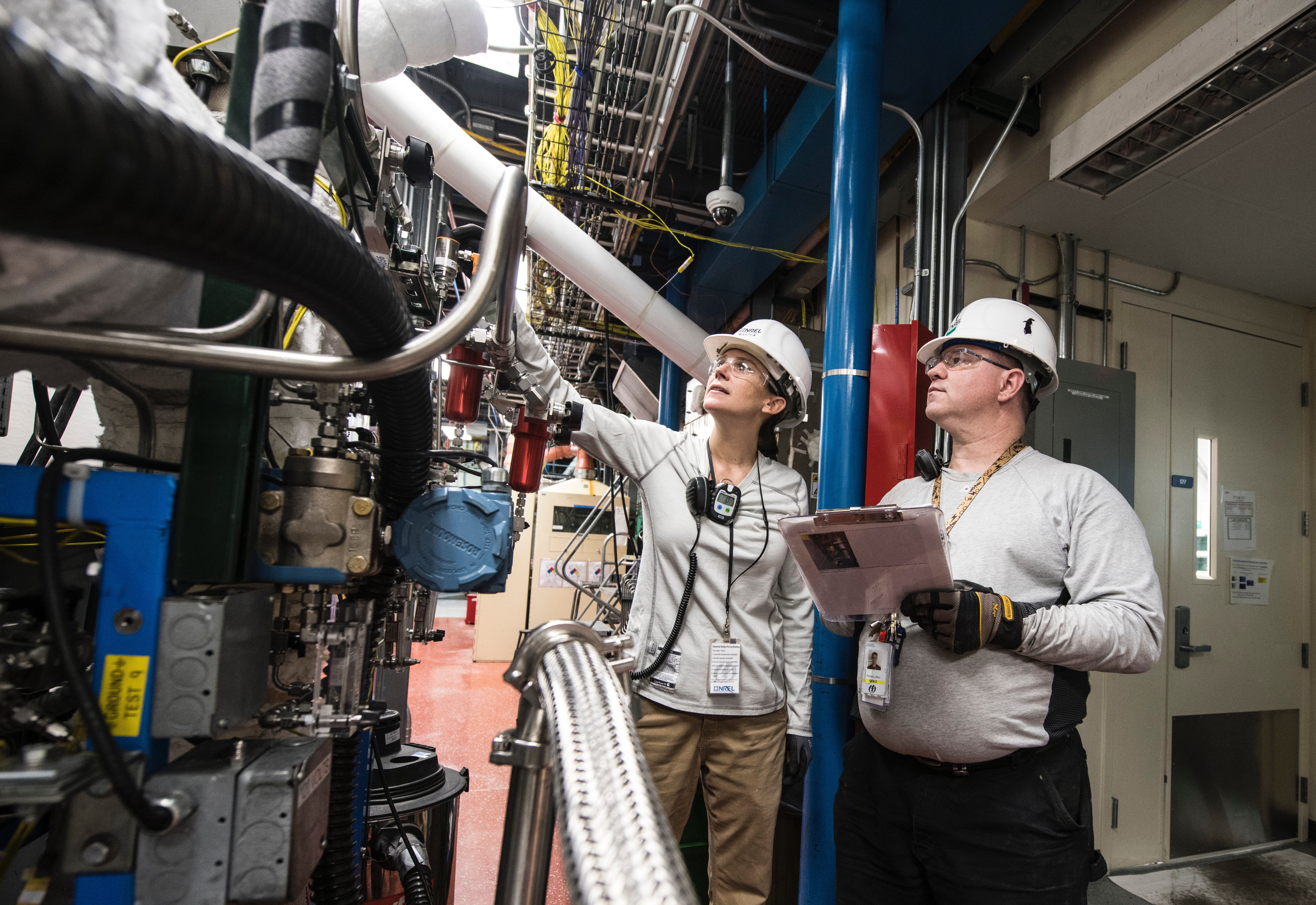
CCSL has established an examination and test centre in Telford, Shropshire, and it really is a state-of-the-art facility. It is here that all our CP courses are delivered.

The Gary McKenzie Training and Examination Centre is an innovative development. We had no hesitation in approving it for courses in cathodic protection in reinforced concrete, and on-land (buried) and marine metallic structures.

Officially opened in May 2021, course delegates have already experienced all it has to offer. This includes ‘real-world’ testing grounds. Yes, course attendees will work on pipes and structures in settings that replicate being in the field. If it’s raining, be prepared to get wet!

When are our cathodic protection courses held?

The Level 1, Level 2, and Level 3 courses last between two and five days. If you are taking the exam, this is a separate one-day event with exam days tagged to the end of each course.

Course dates have been announced for through to September 2022, and there will be more to come. The courses are selling fast, and some are already fully booked. You can find out available dates for your chosen course here:

At the time of publication, depending upon the course, the course cost is £575 and £1,200, with exams costing between £330 and £375. Once you have completed the course and been successful in the exam, you will need to apply to the Institute of Corrosion for appropriate certification.

To book a course, please contact CPA on 01420 471614 or send an email to admin@corrosionprevention.org.uk.

For any further information, or to enquire about membership of the Institute of Corrosion, please contact us.


London Branch Online Meeting 13 January 2022

On 13 January 2022 London Branch had an online meeting featuring

“Life extension of offshore platforms, through retrofit CP design assisted by modelling’’ – Talk by Dr Paolo Marcassoli, Cathodic Protection and Inspections Manager at Cescor, and Istvan Bartha, Independent Subsea Consultant 

Sustainable Engineering: Corrosion Takes Centre Stage

Sustainable Engineering: Corrosion Takes Centre Stage

Corrosion Engineers (and Scientists) Deliver a Sustainable Environment

The Engineering Council recently updated its Guidance on Sustainability. This is becoming a major focus in infrastructure projects, as environmental issues take on ever greater meaning in the modern world.

In this article, we discuss the nature of sustainable engineering, the benefits it delivers, and what role corrosion engineers and scientists play in it.

What is sustainable engineering?

Sustainable engineering is an approach that enables resources and materials to be conserved for future generations so that the environment is not compromised. All fields of engineering are impacted by sustainability issues, and this includes corrosion engineering.

How does corrosion impact sustainability?

Corrosion affects all areas of our society. This includes:

  • The environment; for example, by leakage of pollutive substances from corroded pipelines
  • Critical infrastructure, to mitigate the costs and damage in infrastructure and transport when corrosion is ignored
  • Economic productivity; for example, the closing of plants when machinery and infrastructure is corroded
  • Energy and fuel; for example, when corrosive damage disrupts supply

Corrosion to infrastructure, buildings, bridges, industrial plants, etc. impacts the health and safety of people, national security, and the wider environment.

In short, the more we can do to manage corrosion, the more sustainable we will build, create, and produce.

The benefits of engineering for sustainability

UNESCO has published eight Millennium Development Goals (MDGs) – internationally agreed targets to reduce poverty and improve living standards. Ensuring sustainability of infrastructure helps to increase the welfare of local communities, nations, and regions. UNESCO has identified relationships between physical infrastructure and the MDGs, including:

  • Ports and harbours
  • Airports
  • Highways
  • Factories
  • Education establishments
  • Communication infrastructure
  • Power supplies
  • Irrigation
  • Healthcare centres
  • Public buildings
  • Sanitary infrastructure
  • Water supplies

Understanding how corrosion affects infrastructure, and the comprehensive list of infrastructure that affects attainment of the MDGs, it is easy to acknowledge that corrosion engineering and corrosion science have a huge part to play in creating a more sustainable world.

Successful sustainable engineering helps to reduce carbon footprints, reduce maintenance costs, add value to installations, protect the environment, and improve health and safety.

How can corrosion engineers (and scientists) contribute to a sustainable environment and society?

Both corrosion science and corrosion engineering have major parts to play in the creation of greater sustainability:

  • Corrosion science helps to improve our understanding of corrosion and develop and improve methods to combat and manage it
  • Corrosion engineers are responsible for ensuring that corrosion mitigation processes are put into practice and have the effect they are designed to have

Where corrosion protection is inadequate, the sustainability of equipment, machinery, installations, and infrastructure is compromised. From design through installation, maintenance, and decommissioning, corrosion engineers have a huge part to play in the sustainability of our planet as they:

  • Apply their professional experience to judgement
  • Exceed sustainability regulations by continually challenging boundaries
  • Use resources more effectively
  • Manage risks to minimise the effects of corrosion and maximise the benefits of corrosion engineering

Alasdair Coates CEng FICE MCIHT CMIOSH, CEO of the Engineering Council says:

Sustainable development is an increasingly important issue for society, and the engineering profession works to meet the challenge of the climate emergency. Engineers have a key leadership and influencing role in working towards sustainability, increasingly as part of multi-disciplinary teams that include non-engineers, and through work that crosses national boundaries.

This updated Guidance on Sustainability supports individual engineers in achieving sustainable development through engineering, as well as helping professionally registered engineers – Chartered Engineers, Incorporated Engineers and Engineering Technicians – to meet their professional obligations.

The Institute of Corrosion is committed to sharing our expertise with the world, helping to unlock and manage the effects of corrosion. Our goal – and the vision behind the ICorr brand – is to reduce the environmental impact of corrosion on our infrastructure, enable a more sustainable environment, and reduce the costs of corrosion on business and society.

For more information about our programmes, symposia, and training that help to deliver our vision, please contact us.

(You may also like to read article, ‘7 Benefits to Exploit with Professional Membership of ICorr’ to learn how we help our members achieve their environmental and career goals.)


The problem with black powder deposits

The problem with black powder deposits

The article by Al-Otaibi and Deshmukh (p23 Corrosion Management September/October 2020) provided important insights into how intractable black powder problems can be in hydrocarbon systems. It also reminded Chris Googan of a recent investigation into a black powder problem on a floating production storage and offloading (FPSO) installation. Here’s his anonymised summary of that case…

The Problem

The FPSO operated independently under contract to a major oil producer. In around 2014, a black powder problem became apparent in the gas processing system. The rogue solids periodically blocked strainers at the gas cooler inlets, necessitating shut-down of one of the twin gas processing trains. To avoid flaring the gas, the rate of oil production had to be reduced. Unless the FPSO operator could demonstrate that the black powder problem originated subsea or downhole, its contract required it to carry the costs of unblocking the strainers. It also incurred financial penalties arising from the cut-backs in oil production.

The FPSO Operator’s Investigation

The FPSO operator embarked on an investigation which, unfortunately, lacked both objectivity and any corrosion specialist support. Every time a strainer blocked, samples of the black powder were sent to a commercial laboratory where they underwent comprehensive, and not inexpensive, analysis: wet chemical, infra-red and x-ray spectroscopy and x-ray diffraction (XRD). The FPSO operator’s desire was that the results would identify corrosion of the oil major’s subsea infrastructure, or solids from the reservoir, as the source of the deposits.

In parallel investigations, the FPSO operator also embarked on an intensive, and likewise not inexpensive, campaign of non-destructive testing (NDT) of its own carbon steel pipework and equipment upstream of the strainers. Its ambition was to demonstrate that the topsides gas processing system was not corroding; so the black powder must be originating subsea.

Analytical Results

Chemical Components
Table 1 summarises a typical set of results from some of the many analyses of iron-based deposits collected from the strainers. It also records the presence of other (non-iron) salts found.

If the information in Table 1 were not perplexing enough, drilling down to the crystallographic nature of the compounds, as revealed by XRD, prompted even more head scratching. For example, the sulfate minerals observed included: szomolnokite, melanterite, jarosite and rozenite, which hardly ever appear in the corrosion literature. None is expected to form in anoxic hydrocarbon production environments. It seems most likely that the sulfate deposits were formed by the post-sampling oxidation of iron sulfide corrosion products when exposed to air. This process would be in addition to the known conversion of iron sulphide to iron oxides in the presence of atmospheric oxygen. (It seems that the need to maintain samples under an inert atmosphere was not fully appreciated by all involved). The relative absence of carbonate (siderite) from the majority of samples suggests that the corrosion products were formed when the H2S to CO2 ratio in the gas favoured the formation of sulphide ahead of carbonate.

The whole assessment, however, was complicated by the bewildering multiplicity of other iron-bearing compounds observed in the deposits. These included sulfides: pyrite, mackinawite, pyrrhotite, marcasite and greigite. There were also oxides and oxy-hydroxides: geothite, lepidocrocite, akageneite, wuesite, magnetite and maghemite. Thus, the vast majority of the deposits in the strainers was corrosion product; but the plethora of crystalline forms obscured the corrosion mechanisms; and provided no information at all on where the corrosion had occurred.

In addition to iron corrosion products, small amounts of halite (NaCl) were detected in some; but by no means all, of the debris samples.

Chasing Isotopes

The nucleus of the iron atom has 26 protons; but the number of neutrons combined with these protons can vary considerably. This means that there are 34 known isotopes of iron. Most are exceedingly rare, and of no interest for our purposes. They undergo radioactive decay to daughter isotopes of manganese, chromium or cobalt with half-lives ranging from nanoseconds to millions of years. On the other hand, there are three stable isotopes: 56Fe, 57Fe and 58Fe, with relative abundances of (approximately) 91.75%, 2.12% and 0.28% respectively. Another isotope, 54Fe, has a decay half-life of a mind-boggling 4.4×10²⁰ years; so is stable as far as we are concerned. It makes up the remaining 5.85% of the iron atoms found in nature.

It has been known for some time that there are slight variations in the iron isotope balance for steels, depending on the ores from which they are derived. This prompted the FPSO operator to commission isotope analysis of samples of the debris, and of the process system steelwork. Its expectation was that this would demonstrate that black powder iron did not originate from the gas system steel. The ratios of 56Fe to 54Fe, and 57Fe to 58Fe were measured for nine steel samples and ten debris samples. To cut a long story short: the results were inconclusive. The span of measured isotope ratios observed in the deposits overlapped the span of ratios observed from the steel specimens. Beyond that, no conclusion as to origin could be drawn.

Inspection Results

As with all such exercises, the NDT campaign produced a glut of data, Unfortunately, however, there had never been a base-line wall thickness survey of the as-built pipework. The best that could be concluded, therefore, was that there had only been “marginal” metal loss compared with the nominal values. The FPSO operator interpreted this as supporting its case.

The Corrosion Assessment

After three years of heroic analytical endeavour, the FPSO operator decided it was time to involve a corrosion specialist in the investigation of this corrosion problem. I was commissioned to review the voluminous data and come up with a report that determined whether the operator or the oil major held the responsibility for the black powder problem.

My analysis took a lot less time than my client expected. Instead of delving into the minutiae of what was in the black powder, I focussed on what was not there. The missing ingredient was the salt (halite).

If, as hoped by the operator, the black powder originated subsea, then the only mechanism for it to have entered the gas production system was in aerosol droplets of produced water carried over with the gas from the slug catcher or gas-oil separators. Any such droplets would have to possess a much greater salt content than iron compound content. Incoming produced water analyses showed typical values of 13 000 mg/l chloride, less than 130 mg/l in total of suspended solids, and less than 1 mg/l of soluble iron. Thus, any droplets carried over would have had to contain hundreds, more likely thousands, of times as much halite as iron. Although there was evidence of isolated instances of produced water carry-over, analysis of the solids, and of the water separated from the gas system, simply failed to find anything like enough chloride to tie the iron to a subsea source.

The remaining plank of the FPSO operator’s case, namely that its gas piping was exhibiting only “marginal” corrosion was also soon jettisoned. Elementary calculations, based on the surface area of upstream off-gas pipe wall exposed, showed that even very low corrosion rates, well below those predicted by CO2 corrosion rate algorithms, would result in ample iron-based corrosion product to account for the observed quantities of black powder.

Lessons Learned

Numerous lessons emerged from this exercise. Some related to the original corrosion engineering of the FPSO’s gas processing facilities. For example, hindsight prompted reconsideration of the original design decision to omit the option of being able to inject vapour phase corrosion inhibitors into the system. It also forced a re-sizing and re-design of the strainers.

From the corrosion perspective, however, I offer two learnings. The first, unsurprisingly, is that it is a good idea to involve a corrosion specialist from the beginning of a corrosion investigation. The second, and perhaps more difficult to ensure, is always to keep an open mind when embarking on a corrosion failure analysis. Conducting the exercise with a pre-disposition to an intended outcome invites the risk of a biased and confused investigation.

Chris Googan, antiCORR

Fellows Corner

Fellows Corner

Material Integrity Assessment of Onshore Assets

Onshore oil and gas assets are vast and usually cover a large area. These can refer to all upstream facilities i.e.  facilities used for production and stabilisation of crude, or downstream facilities i.e., refining facilities. Upstream facilities can be divided into off-plot facilities e.g., wellheads, wellhead piping, flowlines, remote manifolds, trunklines/pipelines,
and on-plot facilities e.g., stabilisation systems, separation/dehydrations systems, flare systems, produced water systems, utilities systems,
storage facilities etc.

Typically, these assets are designed for a minimum of 25 years but in the real sense they are used for a longer period i.e., until total reservoir depletion or a halt in production due to global oil and gas economics. Thus, these assets need to be maintained consistently and occasionally optimised to aid production.

A Materials Integrity Assessment (MIA) is a multi-disciplinary review of materials and integrity of an operational asset with a view to mitigate failure or optimise production. This short article outlines the process for undertaking a MIA of an upstream facility.

A MIA can either be proactive or reactive in nature. These objectives are broadly categorised into the following:

  1. To assess suitability of materials when a proposed brown field modification will introduce new production fluids/operating parameters to an existing facility.
  2. To assess the material/integrity threats due to a change in the current operating conditions that can lead to a failure or loss of containment e.g., unexpected reservoir souring, sand production, oxygen ingress, build-up of microbial activity etc.
  3. To proactively ensure the assets are operating within defined limits.
  4. To proactively apply learnings from other facilities and global best practice.

The scope of an assessment can be the whole upstream facilities. or sections of the facility. This needs to be determined by the Client with the above objectives in mind. The scope will determine the duration of the project (from weeks to months) and the number of disciplines involved e.g., where only an on-plot scope is envisaged, there will be no requirement for a pipeline integrity engineer etc.

MIA Methodology

The methodology, and steps of the assessment are shown in figure1 below:

The scope/objective is defined by the Client in conjunction with the MIA Lead. The corresponding disciplines are defined, and personnel nominated.  It is advisable to have a core team and an ad-hoc team on an on-call basis, a typical team comprises the disciplines shown below:

The ICP (Independent Competent Person) should be an experienced professional with no interest in the asset/facility who will be responsible to vet the assessment and to provide guidance where required. Individual and group roles and responsibilities are then defined with the expected time frame by the MIA Lead. It is critical to note the assumptions and exclusions at this stage of the project.  Where there are known integrity concerns, these needs to be highlighted on a draft heat map displayed on a base PFS/PEFS drawings.  The heat map tends to zero in on the areas that need special attention especially when undertaking a review of a very big asset. It also easily shows areas with similar integrity issues or failure patterns that will help with the assessment. 

Data gathering and review is the most critical phase of a MIA.  The data to be reviewed includes. but not limited to, the Facility Design Basis, Plant Operating Manual, Material Selection Reports, Corrosion Management Manuals, Inspection/Monitoring Data, CP Monitoring Data, Failure/Leak registers, Maintenance Plans/Reports, Trending Reservoir Data etc. Some well-organised and maintained facilities/assets will have this information readily available while others may have insufficient information.

Where the available data is insufficient, then several assumptions will need to be made. As an example, in a particular project where there was no baseline inspection data or any subsequent data after seven years of operation, the integrity assessment was then based on a greenfield (new) corrosion modelling. After going through the material selection process, this was then compared with what was physically on the ground and an evaluation made as to whether the right material selection had been made, and the expected remaining design life based on the existing process parameters. This comparison formed the basis of the subsequent recommendations.

A site/field visit is essential as it gives the team the opportunity to visually inspect piping, flowlines and equipment. It also serves as a verification process of the data provided or any of the identified integrity issues.
The visit should also include interviews with key operation and inspection personnel who will be able to give their observations of any changes in the field and more clarity on the plant operations. Pre-prepared questionnaires are recommended for these interviews.

Interdisciplinary Peer Review Workshop

After the site/field visit, the team write up their findings based on the areas of responsibility allotted to each person. The whole write up is then discussed as a team to fine tune and align the findings. On completion of the interdisciplinary review, it is sent to the ICP who will then have a peer review with the whole team. This serves as a form of technical challenge
of the whole exercise and the conclusions/ recommendations.

The report presentation should include a high-level summary using the traffic light system showing the overall status of the asset with the corresponding updated heat map. This high-level summary is based on a more detailed report of the individual areas. This report needs to include a full explanation i.e., scope/objective, overview/history of the asset, findings, where possible photographic evidence and recommendations. This should also be presented visually in a table. An example is shown (top of page 21) based on the earlier heat map.

Recommendations/Conclusions

The recommendations should list out action points to be carried out by the Client in order to verify the integrity of the onshore asset.  These recommendations generally fall into the two categories outlined below:

Short term (less than 6 months) – These require urgent remedial actions/mitigation to avoid loss of containment of hydrocarbon inventory.

Long term (more than 6 months) – These require non urgent remedial actions to be undertaken over a course of time. Advisably between 6 months to 3 years depending on operational constraints.

The completion of the MIA is the presentation of the report (including a power point) to the Client.  Any grey areas need to be clarified to the Client so the recommendations can be addressed within the given time frame.

A Corrosion Management Program (CMP) manual will include the process design and operating conditions, basis of materials selection, corrosion mitigation, inspection strategy as well as corrosion monitoring methodology. The manual needs also to include the risk assessment of critical assets to determine risk severity, monitoring techniques to ensure that the assets can be operated in a safe and reliable manner and the appropriate inspection methods to manage identified risks to maintain the integrity of the critical upstream surface facilities assets. It should also highlight the critical integrity operating window (IOW) parameters and IOW limits to be maintained during service. An IOW programme, its importance, and how to establish
IOW to enhance asset integrity is discussed in detail in reference 2. 
The CMP manual needs to be revised at regular intervals to highlight recent inspection results, risk assessment data as well as changes in process conditions and additional monitoring requirements.

Corrosion monitoring as documented in a CMP manual can be conducted using a number of direct and indirect monitoring techniques, and the merits and limitations of each monitoring technique need to be considered. For effective corrosion monitoring multiple monitoring strategies need to be used and the collected data needs to be analysed along with appropriate process data.  Details of various corrosion monitoring techniques for field applications can be found in the recently revised NACE publication (3). Installing coupons and corrosion monitoring probes can be useful tools for internal corrosion monitoring.  These are considered intrusive monitoring types as they are exposed to pipeline interiors through appropriate access fittings. Proper safety precautions, following the work permit procedures, along with the deployment of suitably trained personnel are necessary for safe removal and installation of coupons from the pipelines during service.  The NACE document “Preparation, Installation, Analysis and Interpretation of coupon data in oil field operations” serves as a useful guideline (4). Corrosion coupons are usually removed at 60-90 day intervals in order to establish long term corrosion rate trends, while the probes are useful to monitor the corrosion rates in real time. Suitable display of the probe’s output in the facility control room will enable the continuous monitoring of corrosion rates, and to alert the operating personnel in the event of higher corrosion rates in order for the required corrective action to be taken. Both wired and wireless configurations are available. The economics need to be taken into account before selecting suitable corrosion monitoring solutions. For pipelines requiring corrosion inhibitor injection, it is essential to have the probes/coupons installed upstream and downstream of the corrosion inhibitor injection point to monitor the performance of corrosion inhibitors. For reliable field corrosion data, it is essential to install the coupons at locations where corrosion is occurring, or most likely to occur, such as high velocity zones, water accumulation spots, etc. Careful location selection is vital since installing the monitoring devices at incorrect locations could obscure the data obtained and its analysis. Linear polarisation probes and electrical resistance probes are used for routine field corrosion intrusive monitoring of the process piping. Linear polarisation probes are commonly used in water systems, while electrical resistance probes can be used in higher resistivity environments. Formation of scales such as sulphide scale, sand erosion, oily/wax deposits at the sensor elements, can affect the accuracy of collected data. As a result, the collected data needs to be analysed carefully to establish a reliable base line reference for meaningful intrusive internal corrosion monitoring data.

In case of nonintrusive monitoring, probes such as thickness measuring sensors using ultrasonic principles can be installed at plant piping exteriors where continuous piping wall thickness monitoring due to corrosion/erosion is warranted, and a number of such systems are commercially available. These sensors can be installed at multiple locations and the wall thickness data, sensor battery life, and the temperature data, can be communicated in real time to the operating facility control room. The main advantage of nonintrusive monitoring is that the monitoring can be conducted when the plant is in service. In addition, critical piping at higher operating temperatures, and at elevated and inaccessible locations can be monitored.  This approach offers cost-savings by eliminating the scaffolding requirements especially for elevated plant piping sections as well as avoiding the costs associated with the operating facility downtime to conduct the conventional thickness monitoring which would otherwise be required. By analysing the collected data, proactive corrective measures to mitigate piping corrosion along with scheduling the piping replacement in advance with the maintenance and operations team can be carried out. This approach enables the monitoring of the critical piping wall thickness condition to prevent the loss of containment due to internal corrosion thus facilitating the operation of the plant assets with highest safety and integrity, as well as to minimise HSE related events. As well as ultrasonic sensors, other methods such as eddy current testing, electromagnetic field mapping and battery free ultrasonic sensors are also considered nonintrusive monitoring types.

To manage critical upstream assets, microbiologically induced corrosion (MIC) also needs to be monitored and managed whenever applicable. Periodic process water sampling to monitor the planktonic bacterial counts, dissolved oxygen content, biocide residuals can be carried out. In oil and gas systems bio-film monitoring probes, samples from removed pipe sections, debris collected during pipelines scraping to monitor the sessile bacteria present in the system along with water quality parameters, provide good information (5).  A number of test kits are commercially available to quickly monitor the biocide residual in the field and to initiate the required corrective actions. It is equally important to document the results and the implemented corrective actions to establish sound historical records.

To mitigate external corrosion threats, parameters such as periodic cathodic protection (CP) potential, current flowing in the structure, CP rectifier potential/current output levels, anode bed condition of underground assets, need to be monitored and managed within acceptable limits. Most of the underground carbon steel piping systems are usually protected by suitable protective coating systems supplemented by properly designed cathodic protection systems. Periodic visual monitoring needs to be carried out at excavated sections of pipelines to inspect the coating condition and to mitigate any external corrosion threats, and the monitored data along with inspection results should be documented.

When selecting the optimum corrosion monitoring solution from the wide range of available options for external and internal corrosion monitoring, the engineering and operational requirements and monitoring objectives, need to be considered, and thus by implementing a robust corrosion monitoring system combined with an effective data analysis, inspection and maintenance strategy, timely remedial measures, the critical upstream oil/gas assets’ integrity can
be managed in an efficient and sustainable manner.

Dr. H.S. Srinivasan, Saudi Aramco

References:

(1) API RP 571-2020 Damage Mechanisms Affecting the Fixed Equipment in the Refining Industry.

(2) API RP 584-2014 Integrity Operating Windows.

(3) NACE TR3T199-2020 Techniques for Monitoring and Measuring Corrosion and Related Parameters in Field Applications,
Houston, TX.

(4) NACE SP0775-2018 Preparation, Installation, Analysis and Interpretation of Corrosion Coupons in Oil field Operations, Houston TX.

(5) TM0194-2014-SG, Field Monitoring of Bacterial Growth in Oil and Gas Systems.