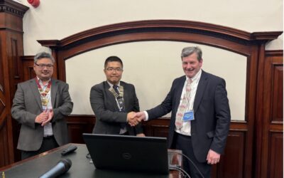
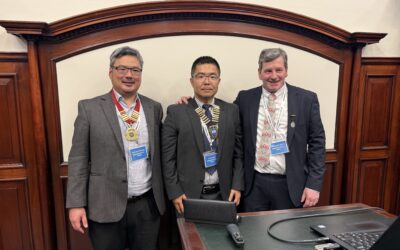
On Tuesday 23rd April 2024 the Aberdeen Branch held its annual joint meeting with AMPP with a talk by Susan Jacob from One Gas entitled: ‘Proportional hazard values for different pipeline coating types, used over the timeline from 1900’s till now’.
Susan Jacob is a Senior Pipeline Engineer in Asset Management for One Gas (Natural Gas Distribution, USA). She has worked for One Gas for over 5 years covering Oklahoma, Kansas and Texas. She previously worked with ConocoPhillips (Aberdeen, UK) for over 6 years as an Integrity Engineer. Susan completed a Masters in Subsea Engineering from the University of Aberdeen in 2016 and also had an internship with Total Energies UK at that time.

The One Gas Company is over 100 years old, and during those years there have been many acquisitions, takeovers, and spinouts of the company. This has resulted in inheriting multiple vintage pipeline systems with different coating types with poor historical records. As part of reducing risk in the system, efforts are being made to record the different coating types and determine their performance. Susan is currently in the process of studying the different coating types to determine their proportional hazards. These considerations will then be input into the company’s risk assessment model. This model will then be integrated into the prioritisation of inspection, maintenance, and replacement work plans.
History of Coating Types
1859: Use of metallic pipe, mainly Wrought iron, for oil transportation started soon after the drilling of the first commercial oil well by “Colonel” Edwin Drake in Titusville, PA. 1920’s – Some operators began to coat the pipe as it was being laid in the ditch, to protect it from corrosion. The idea was to place a barrier between the pipe and the corrosive conditions in the soil, hence the term “the barrier principle.”
1943: NACE (now AMPP) was established by eleven corrosion engineers in response to high levels of corrosion failures reported on pipelines.
1930’s–1950’s: Over-the ditch application of enamels and asphalts during construction continued up to the 1950’s.
The first plant-applied extruded polyethylene mainline systems were developed during the late 1950’s to early 1960’s with liquid-based epoxy coatings (coal tars and asphalts), polyolefin materials (polyethylene or polypropylene), and Fusion Bonded Epoxies. These powder coatings were used either as ‘standalone’ systems or as part of multi-layer system, which really gave birth to the three-layer PP (3LPP) and three-layer PE (3LPE) systems now largely used today.
1960’s saw the birth of trunkline coating systems such as FBE. FBE, a thin factory applied coating, provided excellent flexibility properties, and this was an answer to the failures of many previous materials due to handling and bending of the pipe spools during pipelay and subsequent cracking of the applied coating systems.
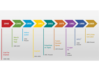
More recently, a new coating technology known in the coatings industry as visco-elastic coatings, and more specifically, polyisobutylene (PIB)-based coatings, has been promoted (by others) which do not age or degrade and remain in a viscous state throughout their lifetime. This is also an environmentally friendly coating repair tool.
The United States Department of Transportation Agency is responsible for developing and enforcing regulations related to the safe, reliable, and environmentally sound transportation of energy and other hazardous materials.
HSE is the UK’s national regulator for workplace health and safety covering a wide range of industries including agriculture. Compared with HSE, though similar, PHMSA (Pipeline and Hazardous Materials Safety Administration) is a federal regulatory body solely dedicated to the safety and regulations of pipelines on a national level.
Failure Analysis and Risk Methodologies
One Gas is keen to make their pipeline operations as safe as possible. Probability risk models are increasingly deployed to assess the risk of failure.
“Risk is the mathematical product of the likelihood (probability) and the consequence of events that result from a failure.” ASME B318S: Managing System Integrity of Gas Pipelines and Chapter 8 PHMSA: Reporting Inspections and Investigations. Susan went on to explain the risk assessment processes in more detail.
Risk Assessment Process
RISK = THREAT x CONSEQUENCE
Key Threats identified by PHMSA:
- Corrosion
- Excavation Damage
- Equipment Failure
- Natural Forces
- Incorrect Operations
- Material Failure
- Other Outside Forces
- Other Causes
PHMSA Consequence Categories are:
- Corporate Image/Reputation
- Direct Economic Loss
- Environmental Impacts
- Health and Safety
5. Regulatory Impacts
PHMSA identifies 3 Categories of Threat Considerations:
Time-Independent (Random) Threats: These threats do not change significantly over time and are often unpredictable:
- Equipment Failure
- External Corrosion
- Internal Corrosion,
- Manufacturing and Construction Defects
Time-Dependent Threats: These threats tend to grow over time and require ongoing monitoring. They are properties such as:
- Environmental Stress Cracking
- Fatigue Cracking
- Hydrogen-Induced Cracking
- Stress Corrosion Cracking
Resident Threats: These threats do not grow over time but may
act when influenced by other conditions or failure mechanisms.
They consist of:
- Geotechnical Hazards
- Mechanical Damage
- Natural Forces (Earth Movement)
PHMSA has been collecting pipeline data since the 1970’s.
Over a 10-year period, there were 1364 incidents and threat causes identified (numbers and percentages, as shown). The second largest category was corrosion with over 20% of incidents over the 10-year period. External corrosion failures accounted for ~36% and internal corrosion was nearly 64% of cases.
Susan explained that in order to measure and evaluate risk in their pipelines they need to move towards a probabilistic mechanistic risk model. To determine such uncertainties one such model is the Weibull’s proportional hazardous model, this aids in evaluating threats in operating systems. This is a complex statistical model which incorporates the Weibull distribution h(t).
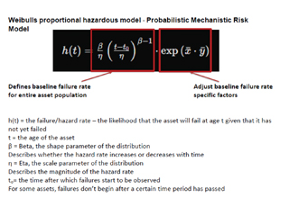
There are two parts to the equation with one part defining the base
failure rate for the entire asset population and the second part makes adjustments to the failure rate. Each type of threat has a model, so for the corrosion threat.
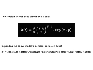
The main factors here are:
- Age
- Asset size
- Coating factor
- Leak history
A coating performance ranking was necessary to be incorporated in order to get input for the model. One Gas has given priority to different coatings based on its studies.
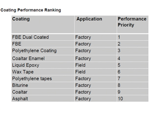
The Company are is still studying and ranking coating performance of pipelines installed in Oklahoma, Kansas and Texas from in 1900s to today. One Gas is currently evaluating 2000 miles of installed pipeline and additional distribution systems and ranking them, but it is believed that the best way to achieve this is to set up accelerated testing within a laboratory which we can then check against the field data gathered for our modelling of performance.
This was a very stimulating presentation by Susan which generated many interesting questions form the Audience.
We thank AMPP our Partner for making this Joint Event possible. Further joint events are planned in 2025 across our UK branches.
On Tuesday 25th June 2024 the Aberdeen Branch meeting was a most interesting talk by Peter Beck and Simon Fenton from IRISNDT entitled: Metallographic Replication of In-Service plant.

Peter is a senior metallurgist with 8 years’ experience split across the power and automotive sectors. His background includes corrosion characterisation in power boilers; materials testing within a UKAS accredited laboratory; and failure analysis of various metallic components from a wide range of industries and manufactured from various metallic alloys. He has significant experience
examining metallurgical
replicas from in-service plants, assessing them for mechanical and corrosion related degradation mechanisms. During his time in the automotive sector, Peter developed standards for structural adhesive bonding and castings for lightweight structures. He currently manages the metallurgical laboratory at the IRISNDT Derby office.
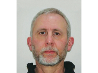
Simon, his colleague, has over 30 years’ experience in the power industry, where he has held several senior technical roles. His key skills are in component inspection and integrity assessment, failure analysis and legislative compliance. He is currently the Technical Manager of Asset Integrity Engineering, based at IRISNDT’s Derby office. This involves working with power station clients to develop and deliver inspection strategies that are aligned with industry good practice, thus ensuring regulatory compliance and confidence that process safety risks are being adequately managed. Simon covers both conventional (coal-and gas-fired), biomass and energy from waste plants.
Peter and Simon went onto describe in detail their work processes, technique constraints and supporting methods deployed.
Metallographic Replication of In-Service Plant
Metallographic surface replicas can provide important information relating to the metallurgical condition of a component, that can have a direct bearing on its fitness-for-service. Such fitness-for-service considerations can include its susceptibility to corrosion and suitability for design mechanical stresses; both of which are key factors when making run, monitor, repair or replace decisions. The condition of metallic materials can be affected by several factors, which primarily include:
- Environment
- Manufacturing defects
- Mechanical stresses
- Process fluids
- Service life consumed
- System design
- Thermal inputs
Replication is often used as part of routine inspection strategies to monitor the material condition over its service life. It is also employed to further evaluate unexpected damage revealed by NDT techniques or after unplanned events such as a fire. It can also be used as part of the quality assurance process for weld repairs.
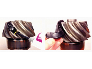
The concept of metallographic replication is analogous to taking a fingerprint. Depending on the condition of the site to be replicated and the information required from assessment, there are two main methods utilised on the plant. For deep defects where surface morphology is required a two-part putty can be used. This takes on the surface contours and sets hard for removal and assessment.
The second and more common method of replication is to polish the metal surface and etch it before partially melting an acetate sheet onto the surface. Once the acetate has hardened it is peeled off and adhered to a glass microscope slide. A curved surface can be flattened for analysis under an optical microscope on-site or in the laboratory.
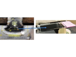
This technique provides the full metallurgical information of the site replicated, which can then be assessed remotely from the component and provides a permanent physical record of the condition of the site at that moment in its service life.
Assessment of the replicated microstructures is typically carried out by optical microscope using bright field illumination. Depending on the degradation mechanism of interest, magnifications of between x50 and x1000 are used. Some of the common degradation mechanisms that can be assessed with respect to corrosion include the presence of sigma. Replication is often used as part of routine inspection strategies to monitor over time. It is also employed to further evaluate unexpected damage revealed by NDT techniques or after unplanned events such as fire. It can also be used as part of the QA/QC process for weld repairs.
Replication vs Direct Assessment
It is not always possible to examine a component directly. Considerations include:
- Access to a component
- Assessment sometimes requires a flat surface
- Capability of portable equipment not equivalent to static equipment
- Component geometry, e.g. crotch position of a branch
There is also a need to retain a permanent record ’snapshot’ for comparison with subsequent assessments. It can be useful in failure investigations to record features prior to destructive testing.
Microscopes and equipment can be taken to the site and set up, but it is not always easy to get good fields of view on curved pipes or in junctions or weldments, so replication is the preferred method to get a flat surface from what may be a curved surface. Replications can also be made of surfaces before they are cut up for study, meaning we have a record of the original, now partially destroyed. Obviously, replication cannot transfer colours of etched/polished surfaces, so these images are black and white, further no compositional information is available. IRISNDT is able to obtain additional materials information on site using an XRF Gun for PMI (Positive Material Identification), which provides broad compositional elemental data and will also undertake strength assessment with portable hardness testers in order to support the replication technique. Replications are effective tools to investigate failure mechanisms in metallic components caused by their circumstances
and environment:
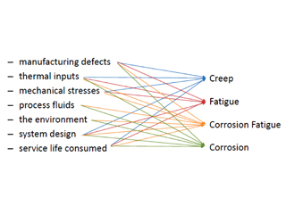
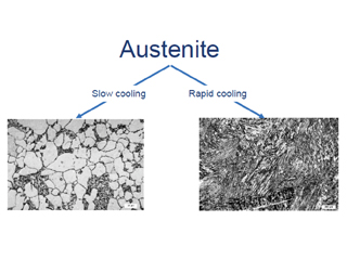
Most of the replication process involves polishing parts on site and taking surface replicants which allow further study by microscope of micrographs of the material structures. This reveals the phase structures of the materials and hence the state of the material can be assessed on basis of phases within them or the heat treatment or working a component may have been subject to.
The other main area of study is that of defects or cracks within the materials. This may be shrinkage cracks or porosity within castings, or, more commonly, cracks within materials at weldments, or as a result of creep, corrosion, or fatigue. While the corrosion product is removed in the process of replica preparation, the nature of the cracks seen can be identified as being from, say, pitting corrosion, corrosion fatigue, or stress corrosion cracking.
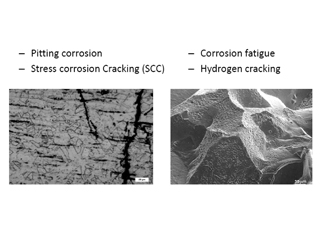
Micrographs here show trans-granular cracking in SCC of austenitic stainless steel. To study corrosion fatigue, the company would look at the crack tips which would reveal oxides as grey amorphous regions in the replicas. Putty type replica method may be used for studying pitting corrosion and hydrogen cracking as this lends itself to capturing more 3D surface information and some measurements can be made with a microscope. The crystalline structure is characteristic of hydrogen concentrations around grain boundaries.
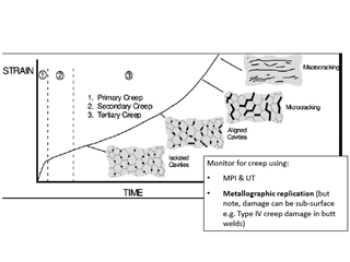
The most common use of replicas in the power industry is to study creep; a process of slow elongation of the steel which leads to cracking. Metal loaded below the yield stress and at about 30-40% of the melting temperature (°Kelvin) can deform and cavities form on grain boundaries. Cavities link to form microcracks and coalesce to give macro-cracking. It is only when macro-cracks appear that IRISNDT can deploy conventional NDT, replication has to be used to identify early stages of creep.
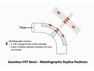
The above illustrates a typical plan for study using replication on a pipe bend to investigate creep phenomenon. Peter and Simon’s Online talk was extremely successful and generated a high volume of questions for this topic, which is rarely presented in such an informative way. During the 2023-2024 Aberdeen Technical Programme, we have been extremely fortunate in sourcing such high quality presentations and we thank all our Presenters for their most valuable contributions. Copies of both of the above presentations may be found on the ICorr website – Aberdeen page.
Future Aberdeen Events
Coming up, 27th August 2024 will then see take place its 2024 Annual Corrosion Forum (ACF), kindly hosted by ENGTEQ Aberdeen on the theme “Corrosion management in the energy sector.” This full-day in-person event is always much in demand, with an estimated attendance of 50 – 70 people, comprising students, technicians, technologists, engineers, scientists, researchers, managers, directors, and other professionals mainly in the energy industry.
Please contact ICorrABZ@gmail.com and see
https://www.icorr.org/events/month/2024-08/
for more information and registration.
The Aberdeen Branch provides a very full technical programme of both in-person and online events. Abstracts of potential papers for the Aberdeen Technical Programme are always welcome for consideration, and anyone wishing to present should correspond soonest with the 2024/2025 Chair and Technical Programme Co-ordinator: meilingcheah@gmail.com
Further information about the Aberdeen Branch, and past
presentations, may be found on their website page:
Aberdeen Branch – Institute of Corrosion
https://www.icorr.org/aberdeen/ under Local Technical Programme and to join the Aberdeen Branch mailing list,
please contact: icorrabz@gmail.com
Susan Jacob – Senior Pipeline Engineer in Asset Management for One Gas (Natural Gas Distribution, USA).
Figure 1: Joint AMPP-ICorr Presentation – Pipeline Coatings Timeline, Cited from Y Frank Cheng and Richard Presentation.
Figure 2: Joint AMPP-ICorr Presentation – Weibull’s Proportional Hazard Model.
Figure 3: Joint AMPP-ICorr Presentation – Corrosion Threat Likelihood Model.
Figure 4: Joint AMPP-ICorr Presentation – Coating Performance Ranking.
Photo 1: Peter Beck – Manager of
the Metallurgical Laboratory at
IRISNDT, Derby.
Photo 2: Simon Fenton – Technical Manager of Asset Integrity Engineering at IRISNDT, Derby.
Photo 3: Use of a Two-Part Putty for Surface Morphology.
Photo 4: Use of Polishing and Etching Technique.
Figure 1: Summary of Inputs and Outputs.
Figure 2: Effect of Heat on Microstructure.
Figure 3: Analysis of Cracking and Fatigue.
Figure 4: Analysis of Creep.
Figure 5: Replication Study Plan for a Pipe Bend to Investigate Creep Phenomenon.


