Branch News – Aberdeen Branch

Following on from the very successful lunchtime webinar series covering Pipeline Coatings, Linings and Cathodic Protection Safety Considerations, with MCF, the branch held its annual joint technical meeting with the Energy Institute (EI) on 26 January 2021 on the theme of, Corrosion Under Insulation – why are we still talking about this?
There were three excellent speakers for this Event – Rebecca Allison (OGTC– Oil and Gas Technology Centre), Yvonne Onuegbu (EI AHI – Energy Institute Aberdeen Highlands and Islands) and Jim McNab (OIS – Oceaneering International Services).

Rebecca Allison, Head of Emissions Reduction at OGTC.

Rebecca Allison, Head of Emissions Reduction at OGTC.

Rebecca Allison discussed the results from a recent survey by Corrosion Radar which showed that over 95% of the O&G Industry felt that management of Corrosion under insulation (CUI) was not currently adequate, and should be up-dated or radically transformed. She noted some industry facts identified in the survey:

  • CUI incurs 40 – 60% of the process plant maintenance costs within the UK Continental Shelf (UKCS), and costs the UK £28 billion every year |rising to an estimated £4 trillion globally.
  • CUI is one of the major causes of accidents in the oil and gas industry, 
since 1984, out of 137 major oil and gas accidents reported within the 
EU, over 20% have been associated with CUI.
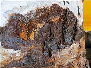
Corrosion under Insulation, an ongoing Issue.

Corrosion under Insulation, an ongoing Issue.

The key components of a CUI strategy are Prediction, Monitoring and Detection:

  • Prediction using data & digital analytics for continuous monitoring to identify where it will occur.
  • Monitoring using sensors to detect moisture and early signs of corrosion using retrofitted and cost-effective instrumentation on Late Life and Brownfield Sites.
  • Detection deploying automated and efficient inspection techniques, although there is a need to push for more investment in new technologies.
    A goal was set 4 years ago by OGTC to eliminate all CUI failures in Oil and Gas fields by 2026 but so far it cannot be said that any significant progress toward this goal has been made. OGTC welcomed the resurrection of the industries CUI Forum with Henrik Andersen, Materials, Corrosion & Inspection Lead at Shell UK Limited as its chair, and which hopefully as an industry, new ways of working and use of Management of Change (MOC) to push through new technologies can be found.

Yvonne Onuegbu (Energy Institute Aberdeen Highlands and Islands).

Yvonne Onuegbu (Energy Institute Aberdeen Highlands and Islands).

Yvonne Onuegbu briefly explained CUI as the external corrosion of pipework and vessels that occurs beneath insulation following ingress of water and corrosive contaminants. There are several Industry guidelines and recommended practices which have been developed, the most prominent being: API RP 583 – CUI and Fireproofing, NACE SP0198 -2017, EFC WP13 WP15, and EI Guidelines for Design, installation and management of Thermal Insulations systems.

CUI presents so many challenges due to the many factors and parameters involved namely, temperature, moisture and contaminants, plus inspection techniques, maintenance requirements and cost. For temperature alone, carbon steel suffers issues from -4C to 175C (mainly in the range, 30 -120C) and for CRA materials between 20C and 200°C, commonly manifesting in the form of chloride stress corrosion racking and/or localised chloride pitting (unless well coated). The moisture or water can be from rainfall, steam discharge, condensation or sweating. Contaminants increase the corrosiveness of the water which comes mainly from the surrounding atmospheric / marine environment, and are often trapped within the insulation materials themselves.

About 20% of pipework failure and maintenance costs since 1994 are due to CUI, so there is good justification to pursue solutions. When trying to investigate CUI the external condition of the cladding can indicate obvious issues if it is disturbed or broken but often intact insulation has to be removed to investigate and reveal corrosion beneath the covering, which has been indicated by other detection techniques, leaks or alarms. Non-intrusive methods of inspection (NII) such as Radiography (RAD), Long Range Ultrasonic Testing (LRUT), Pulsed Eddy Current (PEC) and Guided Wave UT, may be used but they all have their limitations, detection capability, varying speed and cost, with sometimes inconsistent results and individual interpretation issues. RAD in particular can be a slow and hazardous operation requiring scaffolding and containment of the test areas. LRUT is more of a screening tool to indicate general areas where insulation should be stripped off, and (PEC) will detect gross defects but is not so good on minor defects.

Yvonne summarised that for effective management of CUI, the process can be broken down into a structured approach of, investigation, analysis, assessment and mitigation. The assessment process must prioritise the areas considering critical and historical data to focus programmes of work according to the probability of failure followed by Insulation removal, either full or partial.

The CUI Mitigation Strategy involves defining the inspection scope, evaluation technique, and periodicity of inspection and coverage. This stepped approach summarises current industry thinking.

Jim McNab, (Oceaneering International Services).

Jim McNab, (Oceaneering International Services).

Jim McNab then described Focused Stress Concentration Tomography (FSCT) which is a specialised inspection technique for insulated pipelines and being developed by Spier Hunter Ltd in association with Oceaneering with funding from OGTC. The new technology stems from an existing SCT technology whereby an operator wears the inspection tool and walks over the known line of buried pipeline while in operation. It is magnetometer based and it ‘absorbs’ or listens to the magnetic field changes around localised flaws and interprets them as Stress Concentration Zones (SCZ’s). Off-line analysis of the collected data shows SCZ location, severity, pipeline route and depth of burial. FSCT is a ‘blinkered’ version of traditional SCT technology designed to focus the magnetometers and shield them from external magnetic influences. The objectives of this technology are quick screening and real time data interpretation.

A case study showed the evaluation of an un-piggable pipeline which had identified localised high stress concentration zones. DCVG coating inspection also indicated local coating defects. The corrosion under the coating was revealed to have spread some 10m along the pipe past the defect. The FSCT Probe can be mounted on a pipe using a bracelet frame or used as a hand-held unit which is guided over a marked grid by the operator in axial or circumferential directions on pipes in any orientation. This has so far been tested on 4” to 20” diameter samples along with a 5m diameter pressure vessel, and on insulation thickness up to 65mm.
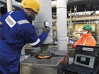
FSCT Probe in use on thermally insulated gas piping.

FSCT Probe in use on thermally insulated gas piping.

The newly developed probe is ruggedised to IP65 and has been tested in operational O&G environments at Flotta Terminal in Orkney and St Fergus Gas Plant installation near Peterhead, but still requires extended data gathering analysis in order to develop algorithms based on real CUI examples, refine the technique, and gain assurance. Future objectives are therefore to determine the limitations of the technology, in terms of maximum insulation thickness, possible stand-off of the probes, and determining how different insulation materials or jacket types influence the results.

Rob Hardy – Commercial Manager, Tracerco.

Rob Hardy – Commercial Manager, Tracerco.

On Tuesday 23rd February 2021, Rob Hardy of Tracerco gave an informative presentation to the Branch illustrating a successful cross-over of medical technologies to the Oil and Gas Sector. Robert holds a master’s degree in chemistry from the University of Newcastle upon Tyne, and has more than 10 years’ experience managing commercial operations in the non-destructive testing market, with knowledge of computer tomography and nuclear magnetic resonance techniques. Robert joined Tracerco in 2019 to focus on the development of the Discovery™ Subsea CT scanning service in Europe, Middle East, Africa and Australia.

Tracerco’s inspection services are now used globally subsea to provide operator with assurance of the integrity of their assets and to diagnose flow abnormalities.
Tracerco have developed the DiscoveryTM unit, which is a diagnostics instrument for pipelines designed to detect wall loss, corrosion, and build-up such as hydrate, sand, asphaltene, scale or wax. It can be deployed on live piggable and un-piggable pipelines, without any interruption to production, or the need for pipeline modifications. Unlike alternative technologies such as ultrasonic and pulsed eddy current methods, that first require expensive subsea concrete coating removal, this method provides a high-resolution image of pipeline contents and pipe wall thickness, enabling pipeline integrity flaws and flow assurance conditions to be accurately visualised.

The unit is deployed using a Remotely Operated Vehicle (ROV) and clamped around the pipe. Real-time communications allow instant assessment of pipeline conditions and different versions are available based on pipe diameter and depth of deployment. The Computerised Tomography (CT) technique used by the Discovery unit is analogous to the medical scanning used in hospitals with a few adaptations to take it subsea. When the CT beam passes through a material the beam is weakened according to its density, which is known as the attenuation co-efficient of the material. Multiple line of site measurements across the items to be scanned build up a picture known as a ‘Tomogram’ which is created by computer reconstruction models. Information about the pipeline wall thickness and integrity is collected in one scan, and complete picture of the pipeline can be fed into integrity pipeline management systems for inspection.DiscoveryTM Subsea Computerized Tomography Scanner.

DiscoveryTM Subsea Computerized Tomography Scanner.

The technology is truly non-intrusive, and with pre-project calibration, it can scan through any coating, such as concrete or polymer, with no coating damage or interference with production. This can be performed at water depths up to 10,000 feet and is capable of scanning 6” to 26.5” pipe ODs using a work class ROV. Features in the Tomograms can be identified by comparing with libraries of known defects, but for extraordinary project challenges, calibrations can be carried out on representative samples.  Rob discussed the principles of collection of integrity / corrosion data subsea and various NDT principles deployed with the Discovery CT Scanner.

In order to assess pipeline integrity and ensure efficient production of assets over time, oilfield professionals are sometimes faced with having to perform pipeline inspection where pigging is not an option or deemed too risky. Previously inspecting a pipeline from the outside was a very costly and often an ineffective high-risk operation. This tool allows online inspection of the pipe from the outside without removing the protective weight coating.

Several case studies were presented to demonstrate how accurate the technique is at identifying aspects of pipe structure integrity and geometry, and wall thickness mapping was shown through concrete weight coatings. Ordinarily the vast majority of concrete pipe seabed inspections require direct contact with the pipeline metal after removal of concrete.

CT Scanning facilitates sections being taken through piggybacked lines and pipe bundles, accurately mapping their internal positioning and misalignments. The technique is ideal for these types of diagnosis as normally the inner pipe cannot be inspected without diss-assembly and the annulus area can be seen in detail. It can expose internal pipes which may have buckled and moved to the wall of the outer pipe and pick up rust formation inside the bottom of the pipe casing.

The technique easily creates images of internal and external dis-bonded coatings and can also be used to identify corrosion under insulation without the need for removal or destructive testing. Internal and external corrosion is readily identified along with pipe wall thinning, positions of weldments and any wall thickness losses through erosion. The technique can also identify thermal expansion effects and even fatigue, as internal pipes can move out to the wall of the carrier pipe maybe through damage to centralisers. Images which are blurred during the scan reveal vibration of the inner pipes during flow.

(Left) Asphaltene @ 1.2g/cc and Gas Pockets. (Right) Scale @ 2.3g/cc. CT scans of internal flow constraints.

(Left) Asphaltene @ 1.2g/cc and Gas Pockets. (Right) Scale @ 2.3g/cc. CT scans of internal flow constraints.


One of the main uses for the technology is in flow assurance and characterisation and location of blockages. About 50-80% of remediation attempts usually fail first time due to lack of information and wrong strategy to clear the product. The scans can characterise the densities of the blockages and therefore determine if the build-ups are asphaltene, sand, scale hydrate or wax. Conversely, identifying the absence of blockages allows operators to modify their inhibition strategy thus reducing the expensive disposal of an environmentally unfriendly product with huge cost savings. Developments in the market for the instrument are in ‘Fast Screening’ with real time data to find points of interest. Full duration scans can then be applied or automatically triggered wherever an anomaly is identified to detail and diagnose the features.

The latest information about branch events can be found on the diary page of this magazine and at: https://www.icorr.org/events/category/aberdeen-branch/list/

All Aberdeen events (both presentations and associated Q&A) are recorded and may be found at: https://www.linkedin.com/in/aberdeen-icorr/

Follow us on social media

General Enquiries

Institute of Corrosion
Corrosion House
5 St Peters Gardens
Marefair
Northampton
NN1 1SX

tel: + 44 (0)1604 438222
e-mail: admin@icorr.org

Related News

Institute of Corrosion 2024 AGM at Neville Hall

Institute of Corrosion 2024 AGM at Neville Hall

“The Institute offers its many congratulations to our newly elected President – Dr Yunnan Gao”
At the AGM of November 13th held at NE Branch, Stephen Tate passed on the Presidency of ICorr to Yunnan Gao and Yunnan passed on the Vice-Presidency to Anthony Setiadi.
Yunnan brings a wealth of experience to ICorr in many areas of Corrosion Management and has the full support of Council and employer bp.
Anthony also joins with considerable experience in many areas including renewables and Offshore Wind in his extensive work with Wood Thilsted. Together our new Team will move forward with renewed success.