Ask the Expert
Question:
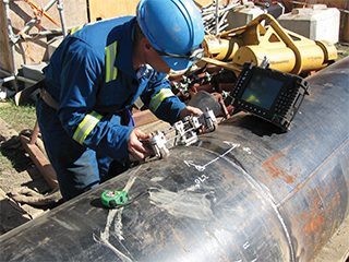
What errors are most likely to occur when measuring dry film thicknesses on steel, and how can they be avoided. PS
Answer:
Dry film thickness measuring probably causes the most conversation/arguments on site than anything else, this is normally born out of the absence of an inspector test plan or no conversation/agreements with client/contractor/inspector.
Errors made during dry film testing are due to several reasons, including due to taking measurements before the paint or paint system is hard dry. A contractor will paint until the job for the day is done, and of course this will continue well into the afternoon, then the Inspector, or Supervisor will take a measurement with a dft gauge. If the paint is not ‘hard dry’, the probe will push into the coating giving an incorrect lower reading than may have been expected. Before taking a dft reading, ensure the paint is hard dry by pushing a fingernail into the paint. If the fingernail leaves a depression, then the paint is not hard dry. If of course no depression is left, then the paint is hard dry.
However, the most common error is not calibrating the measuring device to the same blast profile as the uncoated steel. Often this is not possible, so alternative calibration methods need to be used, as described below.
(1) Measure the blast profile before application of the paint, and after applying the system allow to become hard, then measure the dry film thickness using a digital gauge (or other). Then subtract the blast profile to give the true dft of the paint system. For example, if the steel surface has a typical profile after blasting of 50 microns, and the applied paint measures 300 microns, then then total dft is 250 microns (covering the peaks of the blast).
(2) Calibrate the dft gauge using a surface profile comparator to the expected surface profile, and then accept that the measured dft is the correct reading.
(3) Calibrate the gauge on a piece of smooth steel, then measure the dft of the paint, and subtract 50 microns as being the nominal blast profile.
Whatever method is used it must be agreed pre-contract and should be included in the inspection test plan. In the absence of a test plan, one should be created and accepted by all parties before painting commences, this prevents disagreements at a later stage.
Kevin Harold, Paintel Ltd
Answer:
Dry Film Thickness or (DFT) is probably the single most important measurement made during inspection, or quality control of a protective coating application. Even the most basic coating specification will inevitably require the DFT to be measured, which is considered to be the most important factor determining the durability and longevity of a coating system. The thickness of each coating layer in a system, and the total system DFT will have to be measured and recorded to show that the specified system will meet the desired durability.
There are many mistakes which can be, and are often, made when measuring DFTs. Often its believed that it’s a case of simply putting a probe on a coated substrate and taking the measurement, and that’s where the numerous issues occur.
DFT is typically recorded with either a magnetic pull-off gauge (Banana gauge or Type 1) or an electro-magnetic constant pressure probe gauge (Type 2). Both these types of gauges are non-destructive (will not damage the protective coating during the inspection) and are the most commonly used methods for measurement of film thickness of protective coatings.
The Type I gauge works by recording the magnetic force needed to pull off the gauge from a ferrous substrate. Simply a barrier or a coating between the substrate and the gauge’s magnet reduces this magnetic attraction, which can then be measured i.e. the force required to pull the gauge magnet from the coated substrate is shown on the gauge as the film thickness of the coating material.
There are benefits in using a type 1 gauge, however there are often great challenges for an inspector with calibration, which has proved to cause major problems on projects. For example, determining the Base Metal Reading (BMR). For accurate calibration of Type I gauges the standard SSPC PA2 specifies that after calibration using a NIST test standard, or equivalent standard DFT shim with traceable calibration, that a measurement of the blast profile should be taken in order to achieve an accurate DFT reading as possible. This is not 100% accurate and can affect the resulting DFT reading. This BMR measurement is carried out on the blasted surface using the Type I gauge and which depicts an imaginary magnetic line in the blast profile This reading is always deducted from the final average reading of the DFT. This is typically done with a banana gauge or Type 1 DFT measuring gauge. Before use the BMR and NIST Standard deviation must be carried out and recorded, the inspector should always remember that the gauge should only be used on non-metallic coatings on a metallic or ferrous substrate.
However, the Type 1 gauge is ideal for use in environments where the use of electronic instruments is difficult, e.g. inflammable atmospheres in oil and gas production, and for underwater# dry film coating thickness inspection.
Type II gauges or the constant pressure probe gauge works by measuring changes in the magnetic flux within the probe of the gauge, the probe must remain in contact with the substrate during the reading or measuring process. The Inspector should be aware that the following may affect any readings taken.
• The magnet should be clean and free from surface contaminates such as iron or steel grits the inspector should also check the substrate is free of any contaminants which may adhere to the magnet prior and during DFT inspection.
• DFT readings should be taken only when the protective coating film is dry as if the coating is uncured or tacky the actual film will hold the magnet past the point when the magnet should have detached.
• The inspector should note that vibrations may cause the magnet to release prematurely resulting in a higher or inaccurate reading.
• Readings should generally not be taken within 25 mm or 1 inch of an edge as the magnetic fields in this area will interfere with the magnetic forces between the substrate and the gauge.
• Always ensure that you have a spare battery or a Type 1 Gauge for back up.
As with the Type 1 gauge, the Type 2 gauge must be calibrated with a traceable DFT shim on an uncoated area in order to account for the blast profile before any measurements are taken.
There are also other instruments used for DFT measurements, but which will damage the coating film. The most commonly used instruments are the Paint Inspection Gauges (PIG gauges) or Tooke gauge. These instruments are termed as destructive test methods due to the necessity to cut into the paint film to obtain the measurement.
A further issue with DFT measurements, and the one which causes the main issues on site is frequency of testing. The specification should always state the requirements for frequency of DFT measurements and film thickness acceptance criteria, or at the very least specify a standard to which DFT measurements should be carried out in accordance with. The number of measurements that will be made is important to all parties involved in coating works. The contractor and inspector obviously need to be in sync with requirements for such an imperative measurement and not to confuse one another in the field.
Lee Wilson, Corrtech Ltd
Ask the Expert
Question:
At a recent meeting with a client a question was raised – How does my company find a corrosion engineer who has a broad background over a range of disciplines? They reported that they have tried to recruit, but can only find people with specialist training in limited areas. To cover all our corrosion needs, we would need to hire a paint inspector, a welding inspector, a CP engineer, a metallurgist, a concrete specialist and a water treatment engineer. Surely there must be people who have a basic knowledge of these disciplines who could carry out day to day work and be able to call in specialist experts when needed? AN
Answer:
The question is not unusual in the current economic situation. Many companies know that they need experts for some jobs but require a more generalised approach to everyday situations. At one time, larger companies ran training programmes for new engineers, to enable them to become familiar with the company’s products and processes, and to provide them with a broad experience of the various corrosion challenges that they would meet during their working lives. Often this was an informal apprenticeship, with the new starter shadowing an experienced engineer and gaining knowledge and expertise over time, perhaps a couple of years. A similar situation may be like that of a junior doctor, who has the opportunity to work in many different healthcare situations before deciding on a specialism.
The result of the informal apprenticeship type process would be an engineer who understood the corrosion aspects of the operation of multiple areas of that plant and who was able to use that knowledge for the benefit of the company at other sites and with other processes. Unfortunately, the need for greater productivity and profits, in combination with the drive towards minimal workforce numbers, has significantly reduced the opportunity for the “grow your own corrosion engineer” approach in all but the largest or most determined companies.
In parallel, there has been an increased requirement for new starters being able to show “paperwork” which demonstrates training and competence in specific areas. Whilst this has reduced the number of “corrosion cowboys” in the industry, it has also resulted in many good corrosion engineers with long term general experience, being unable to “prove” their knowledge. People who went through the on-the-job multi-discipline corrosion training were not provided with a certificate, and after a number of years of experience when they may be looking to change company or diversify out of a career limited industry, are finding it difficult to convince potential employers (who now need certificates as proof of knowledge) to hire them.
In turn, these companies are finding that most of the potential new employees are often qualified only in one specific discipline and therefore they may need to hire several people to cover the range of job requirements – the problem of the client at the start of this article.
One option for the company, is to hire specialist corrosion expertise when it is needed, but again this can be a challenge. How does the company know what sort of expert they need and what happens if the problem covers too many aspects for the expert? What if they need a person with a general corrosion knowledge? Of course, there are large consultancy companies which employ several specialists and can match the enquirer with a person in the right specialism. But again, what happens if a more lateral approach to the corrosion problem is needed?
As one semi-retired senior corrosion engineer, with a lifetime of broad experience, said, people like us are literally dying out. I need to recruit my replacement but how?
To meet the needs of individuals who want to increase their general corrosion knowledge or have their experience recognised in a paper format, and companies who want to take on a corrosion engineer with a certificate demonstrating a broader background knowledge, the Institute of Corrosion has developed a Fundamentals of Corrosion for Engineers (FOCE) course. This course aims to be a solution to fill both the general corrosion engineer’s certificate gap and an employers need to find a general corrosion engineer with a relevant certificate of knowledge.
Starting with the very basics of the corrosion reactions, the course builds up over an intensive week to cover a wide range of corrosion situations and industries. The classroom based FOCE course aims to provide the attendees with a general understanding of the common corrosion factors which link apparently different industries. Whilst not a substitute for several years of hands-on training, it gives the participants an awareness of a range of corrosion challenges and solutions across common industries, thus providing a background knowledge of fields that people may wish to investigate further, and work in, as part of their career journey.
In addition, passing the examination at the end of the course provides the successful candidate with a ‘Certificate of Achievement’ from a globally recognised Corrosion Institute. The certificate demonstrates the broader corrosion knowledge that some employers are seeking when recruiting a general corrosion engineer and provides confidence for the employer that the new engineer does have a wider understanding of corrosion situations. The experienced corrosion engineer will also gain relevant paperwork which both backs up their knowledge and fits company recruitment policies.
FOCE courses are held regularly (covid restrictions permitting) with dates and locations being listed on the ICorr website at www.icorr.org/training-qualifications-2-2. The next course is on 15 – 19th November 2021.
Jane Lomas, Amtec Consultants Ltd
Ask the Expert
Question:
What is the best approach to detect and monitor CUI ? CL
Answer:
The most reliable method to detect and monitor CUI is a full strip of the insulation and visual inspection, although once CUI is detected with this method it is rarely monitored. The key disadvantage of this approach is the high cost and required resources associated with access, stripping, possible refurbishment of the coating, and reinstatement of the insulation. The need for a reliable screening technique to focus CUI inspection efforts has been recognised for many years. Various non-destructive techniques (NDT) are available to detect CUI directly without removing the insulation, such as real time radiography (RTR) and pulsed eddy current (PEC). However, the drawback of these techniques is the uncertainty around probability of detection (POD), despite significant technique improvements in recent years and development of technologies through joint industry projects such as those done by HOIS (Harwell Offshore Inspection Service). Possible presence of CUI can also be detected with indirect techniques which are based on detection of water or humidity in the insulation system. Techniques such as thermography, neutron & x-ray backscatter, and more recently various types of sensors are all capable of detecting water or humidity but similar to direct methods there is still uncertainty around the POD and questions about the reliability. Another drawback is that detecting water does not necessarily mean that CUI has occurred at the points where water is located. Much development work continues especially with sensors which may offer better monitoring capability including direct detection of corrosion. Improving CUI predictive capability through greater sharing of data and analysis can also help focus where to inspect, but the CUI still needs to be located and there are many instances of CUI “surprises” in the industry especially if 100% stripping of insulation is not done during service of the facility. It should also be recognised that it can take 15 to 20 years to fully validate CUI technology developments and therefore compromises will inevitably be sought. A complementary approach involving direct NDT, water detection, sensor monitoring and the application of better data analysis and CUI prediction is probably the optimal way forward to focus efforts with CUI inspection planning, but full strip and visual inspection remains the most reliable approach.
Steve Paterson, Arbeadie Consultants
Ask the Expert
Question:
“How do you know when the pot life of a 2-component paint has expired ? Can you extend pot life, if so, how?” PS
Answer:
The reaction or cure of a two-component paint or coating is initiated when the two parts are mixed together. The manufacturer will state a pot life at a given temperature on the product data sheet.
Generally speaking the reaction rate doubles for every 10 degrees C increase and halves for every 10 degrees C reduction in temperature, this can be used to estimate the pot life at different temperatures if this is not stated on the data sheet. The age of the product can affect the pot life, depending on the chemistry of the particular product this could produce a longer or shorter pot life. Furthermore, the type of pump, fluid friction and pressure in the pump also have an effect and therefore it is also good to know the signs of when the material is towards the end of it’s pot life.
There are other variables in material chemical composition and properties such as the viscosity, lubricity and level of fillers but generally speaking a sudden increase in blockages, viscosity, reduction in fan pattern and atomisation are a sign the material is past its best, also most reactions are exothermic therefore the product will start to get hot.
One method that can be used for extending pot life at higher temperatures is cooling the product, or cooling the pump. Care should be used when cooling the product as it could be below dew point and take on moisture during mixing and atomisation.
Some products have a pot life inhibitor available to increase pot life in hot climates, this is mixed into the product prior to adding the Part B and applicable to products cured by free radical polymerisation. Some products are also available with tropical or winter grade hardeners.
Any attempt to extend a pot life after mixing will affect the final cure and other properties of the material and could poison the reaction completely, for example mixing in additional solvent. Of course solvent should only be added when it is recommended by the manufacturer and only up to the maximum percentage stated.
Phillip Watkinson, Corrocoat
Ask the Expert
Question:
What are the advantages and limitations of impressed current CP compared to sacrificial anodes, and where would you use one opposed to the other? BK
Answer:
In order to help readers of Corrosion Management to understand the differences between impressed current and sacrificial anodes cathodic protection systems, let me to start with a brief definition of both systems, where they are installed, type of anodes, sources of energy, and finally indicate what their advantages and limitations are. In both applications, CP current flows from the anodes, through the electrolyte to the structure being protected.
Impressed current systems
The impressed current systems use an external source of energy to provide direct current for cathodic protection. Generally, they are used when large quantities of protective current are required, for bare structures, those with poor coatings, or when the resistivity of the electrolyte is over 5000 Ohm-cm. They are also used for most long
buried pipelines, irrespective of coating quality and for above ground storage tank bottoms, seawater intake systems, interiors of fresh water tanks, well casings and many ship hulls. They are used for some piers, jetties and offshore structures if power is available.
Types of impressed current anodes
Dimensionally Stable Anodes: Substrates of titanium and niobium with coatings of platinum and mixed metal oxides (MMO) of ruthenium and iridium. Presently MMO/Ti are most commonly used.
Ferrous Metals: iron-silicon-chromium, iron-silicon-chromium-molybdenum, iron with high silicon, cast iron, carbon steel, stainless steel. Presently Fe-Si, with Cr in chloride rich areas and Fe-Si are most commonly used. Anodes of magnetite (Fe3O4) are also used.
Lead and graphite-based materials have historically been used but the superior performance of the materials above has caused the cessation of their use. Coke breeze is widely used in conjunction with suitable anodes, in buried applications, to effectively decrease resistance and increase life.
Non-ferrous metals: aluminium and zinc are used in some very specialised applications and copper in anti-fouling systems.
Energy sources
Transformer Rectifiers: single-phase or three-phase, extensive range of input voltages (120, 220, 480V AC), cooled by air or oil, typically with silicon diode rectifiers; these deliver low voltage DC for the cathodic protection. They can be simple constant Voltage, or constant Current and or Potential Controlled. The second are used when the design needs constant level of current. The last when it is required to automatically adjust the output to maintain constant structure/electrolyte potential with respect to a permanent reference electrode. Mains electricity and transformer rectifier normally provide the lowest cost and highest reliability impressed current for CP.
Solar Energy: utilised in those locations where there is no commercial power source available. They require batteries to deliver CP power at night and poor weather when solar energy is not available.
Wind Energy: is used where there is no electric energy and the solar energy is limited. They require batteries to supply current when there are no winds.
Thermoelectric Generators: utilised as a low voltage DC supply in remote places where there is availability of hydrocarbon fuels (e.g. natural gas, methane, propane). They are high technology equipment and require periodic maintenance.
Galvanic anode CP systems
Galvanic anode systems deliver CP current due to the difference of the electrochemical potential between them and the structure. The anodic materials is more active in the electrochemical or galvanic series of metals than the structure material. Galvanic (or sacrificial) anodes are generally used in environments of low electrical resistivity. Typical applications are: offshore oil and gas platforms and pipelines along with offshore wind foundations, ports and harbour facilities. These are all quite high current applications Smaller current applications are those such as short sections of buried pipelines, internals of flooded vessels or structures like barrages, oil field production vessels, water knock outs, desalters and separators, water storage tanks.
Types of galvanic anodes and uses
Magnesium: Soils, typically with resistivity up to 10000 ohm-cm, typically pre-packaged with a backfill of gypsum (75%), bentonite
(20%) and sodium sulphate (5%). Can be used in ribbon form.
Zinc: environments with resistivity lower than 2000 ohm-cm. Cn be used in soils with backfill of gypsum (50%) and bentonite (50%). Deficient operation in electrolytes that contain bicarbonate, carbonates and nitrates. Limited to temperatures up to 60°C. Can be used in ribbon form.
Aluminium: The main use of aluminium alloy anodes is in seawater and marine sediments environments, such as offshore platforms and pipelines. Deficient operation in electrolytes of pH alkaline (>8); in closed compartments with no replenishment can cause significant reduction in pH and inadequate performance.
|
Cathodic Protection System
|
Advantages
|
Limitations
|
|
Impressed Current
|
Significant range of driving voltages and higher
and adjustable current outputs
Operation in extensive range of resistivity
Great variety of anodes with very low rates of consumption
Electronic control and monitoring can be advantageous and reduce inspection and maintenance costs. Often essential in severe fluctuating DC traction interference
Can be operated at constant current or constant potential adjustment
Reliable onshore and if properly maintained, on ships
|
Require external source of energy
More likely to generate stray current interference
to foreign structures than galvanic anode
Susceptible to deterioration by external conditions, particularly offshore
Require monitoring of potentials for safe operation to avoid over and under-protection
Offshore systems may have high inspection,
control and maintenance requirements
More complex and in some applications, less
reliable than galvanic anode systems
Electronic control and monitoring can cause additional complexity and lower reliability
|
|
Sacrificial Anodes
|
Robust, simple and reliable
Generally easy installation and few components
Low costs of installation and maintenance
Do not require external sources of energy
Generally cause limited interference or interference problems with other structures
|
Limited driving voltage
Low and limited current output from individual anodes
Life is a function of the anodic mass
Attacked in acid environments
Operation affected by the environment resistivity
CAPEX can be higher than impressed current systems, but, generally, OPEX is generally less
|
Question:
What is the impact of corrosion on the offshore renewable sector, and how is this being controlled? AN
Answer:
The world is depending more and more on clean renewable energy as opposed to that based on oil and gas, and the renewable sector is rapidly becoming one of the biggest energy sectors in the world, with wind farms breaking records for output and size. However, with these farms come many of the same corrosion and engineering challenges that have been faced by the oil and gas sector for many years. Corrosion is a major risk for offshore wind foundations, its effects could mean costly offshore retrofit work, resulting in the loss of energy generation, and expose operatives to additional health and safety risks. Corrosion protection is thus of vital importance to assure the integrity of offshore structures, to minimise exposure to these risks.
It is estimated that the cost of painting an offshore structure in a dedicated painting facility can be up to 25 percent less per square metre compared with coating onsite. In addition, costs brought about by repair work to a new coating system carried out onsite have been estimated by one coating manufacturer to cost up to 5 to 10 times more per square metre compared with repairs made in the shop. A report by TWI stated that a recent coating failure on a wind farm off the coast of Ireland cost over £2m to rectify, 20 times the cost of the original installation itself
Thus, it makes sense to complete the corrosion protection of any structure in a paint shop or facility straight after fabrication—including painting, inspection and any necessary repairs. A corrosion protection strategy should be an integral part of the production process, and an appropriate time frame allocated in order to successfully execute the painting programme prior to delivery. It’s a simple concept, in order to increase quality and reduce costs, owners must ensure the dedicated site team includes a corrosion control specialist during design, construction, and commissioning, in order to ensure that the work is carried out on time and to the required specification.
Most of the standards available for offshore corrosion protection of wind turbine towers have been used in the oil and gas sector industry for many years, including ISO 12944 and NORSOK M-501. However, it is often seen in the recruitment adverts for corrosion control and QA/QC personal, the requirements being specific to the renewable sector, many whom are not familiar with the oil and gas sector, which in turn has created its own issues and subsequent failures and delays to project execution.
There are a number of different wind tower structural configurations, and these can a have an impact on the protective coating system applied. Although the external corrosion at the splash zone and tidal areas has been of great concern to the industry, particularly when dealing with the stress and fatigue related parameters of the towers, this corrosion in general is well understood and very similar to the challenges observed across other offshore facilities. However, internally, in the closed compartments, the current guidelines and standards are inadequate, as with data from inspections and surveys becoming available, major Issues such as fatigue and stress issues, design and material selection, cathodic protection, need to be addressed.
Experiences with internal corrosion have shown that it is difficult in practice to completely seal compartments and render them airtight. If the closed-compartment structure is not properly sealed, direct ingress of air is certainly possible. One major certification society has noted that seawater and air (oxygen) ingress were detected in foundations that are as new as two years old, which increased the rate of corrosion and localised corrosion attack. After the commissioning of monopile foundations in many offshore wind farms, corrosion problems have been observed inside of the monopiles in the area located beneath the so-called ”air-tight deck”. The cause of this corrosion has been usually a failure of the subsea cable entrance seal which allows air (oxygen) to penetrate into the monopile. This is in complete contradiction to the assumption that the submerged internal area is a ”gas-free” area, with a low corrosion risk due to a limited presence of oxygen after initial oxygen depletion. There is also a risk of microbiologically influenced corrosion (MIC) in a closed-compartment foundation, with localised corrosion attack on the submerged surface and in the portions of the monopile buried in the upper region of the sediment. Alternating aerobic and anaerobic conditions may also favour bacteria growth, and the risk of MIC depends on the bacteria species and the environmental conditions present. Sulphur-reducing bacteria (SRB) are expected to be present, and if growth conditions are favourable, then sulphide production can occur. Differences in the state of the tide result in variation of the water level inside the pile, and this has led to micro-organism in the seawater, that do not require oxygen to survive, such as SRB. Some suppliers insist on placing cables inside the tower going through the pile and leaving the structure through a hole below the water known as the rat hole which is sealed. This seal has proven in many cases to be inadequate and again allows water ingress into the pile.
The offshore wind energy sector is facing major challenges and not fully addressing the corrosion issues, nor implementing strategic corrosion management systems from the design stage, due in part to the demand pressures for supply to meet the energy requirements.
Lee Wilson, Corrtech Ltd.
Ask the Expert
The question in this issue features solvent free epoxy coatings. Readers are reminded to send in their technical questions for possible inclusion in this column in future.
Question:
I wish to use a solvent free epoxy coating to lower the environmental impact of my maintenance painting project, however when I look at the products available there appears to be a wide range of volatile organic compound (VOC) content in such coatings. Why does a solvent free epoxy coating contain VOC , and what is the difference between a solvent free epoxy, and a 100% solids epoxy coating? PF
Answer:
A 100% solids epoxy coating contains no solvents, no VOC and retains the same level of thickness from the time they are applied to the time they dry. There is currently no clear universal definition of a Solvent Free Epoxy Coating. The generic name indicates that the epoxy coating should be “solvent free”, but when looking at these coatings in the market today, we see that that is not always the case. To be able to spray apply such a solvent free coating through single feed airless spray equipment, the viscosity needs to be low enough to get a good spray pattern without the need for thinning with solvents. A very common formulation approach for solvent free epoxies is to use low viscosity liquid Bisphenol A or Bisphenol A/F epoxies that have been modified with reactive diluents. The epoxy binder is cured with low viscosity polyamine or polyamide curing agents that can be supplied with 30% benzyl alcohol as a solvent to further lower viscosity, and which is compatible with the epoxy, and aids the cure. In many cases the viscosity needs further reduction to reach optimal application properties, so 10 weight % or more benzyl alcohol solvent can be added as a non-reactive epoxy resin diluent.
Without any scientific proof (that we are aware of) benzyl alcohol has been claimed to remain as a solid in epoxy coatings, but benzyl alcohol is an aromatic alcohol with a boiling point temperature of 205 C and should strictly speaking (in our opinion) be classed as a solvent, and contribute to the coating’s VOC [1] content. Some argue that due to benzyl alcohol’s high boiling point temperature most of it will not evaporate or diffuse out of the coating film. There is however a reason why over the last two decades we have seen solvent free epoxy coatings for potable water tanks move towards benzyl alcohol free formulations as it has been observed that over time the solvent diffuses out of the coating film giving taste and smell to the potable water [2,3]. The significantly lower practically determined volume solids, compared to the values calculated treating benzyl alcohol as a non-volatile, is a strong indication that it is in fact volatile and should be classified as a solvent.
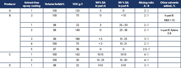
The benzyl alcohol contents in the epoxy base and curing agent part of marine solvent free epoxy tank coatings taken from the coating manufacturers material safety data sheets, are shown in table 1.
Table 1. Benzyl alcohol (BA) content in some typical marine solvent free epoxy cargo and potable water tank coatings.
From the table it is clear that not all paint manufacturers count benzyl alcohol as a solvent that increases VOC and lowers volume solids of the coating, so we get the unfortunate situation that solvent-free coatings that should have very close to 100% volume solids and VOC 0 g/l can vary anywhere between 95 – 100% solids, and 0 – 180 g/l in VOC. Considering that ultra-high solids epoxy coatings can have up to 97% VS and down to 50 g/l in VOC, a universal common definition of solvent-free epoxy needs to be made so that users can clearly distinguish between solvent free, ultra-high solids epoxy coatings, and 100% solids epoxy. As the main advantages of solvent free epoxy coatings are very low or no VOC emissions, the possibility to apply thick coating films with little or no film shrinkage and lower film formation stress.
Based on work we did more than a decade ago, we would like to propose the following universal definition for a solvent free epoxy coating to avoid confusion by users. Hopefully, this will start a discussion among relevant stakeholders to agree on a common clear and universal definition.
Michael Aamodt, Alan Guy and Raouf Kattan, Safinah Group
“A ‘solvent free epoxy’ coating can be defined as an epoxy paint where all of the non-reactive components of the formulation have an initial boiling point greater than 250 C at an atmospheric pressure of 101.3kPa. Benzyl Alcohol added to epoxy coatings should be counted as a volatile since it is not reactive and falls within the definition of a solvent according to EU Paint Directive 2004/42/CE. Benzyl alcohol will also lower the practical volume solids compared to that calculated and often stated on data sheets, when assuming it is non-volatile. At the same time its inclusion increases the volatile organic compound (VOC) content of the coating.”
References
1. “Directive 2004/42/CE of the European Parliament and of the Council of 21 April 2004 on the limitation of emissions of volatile organic compounds due to the use of organic solvents in certain paints and varnishes and vehicle refinishing products and amending Directive 1999/13/EC”.
Official Journal L 143, 30/04/2004 P. 0087 – 0096.
2. J. Romero et al. “Characterization of Paint Samples Used in Drinking Water Reservoirs: Identification of Endocrine Disruptor Compounds”. Journal of Chromatographic Science, Vol. 40, April 2002.
3. Aamodt, M., “Eco friendly coatings for potable water tanks offshore”, Offshore Marine Technology, 1st Quarter 2010, 20-21.