Fellow’s Corner

This series of articles is intended to highlight industry-wide engineering experiences, practical opinions and guidance, to provide improved awareness for the wider public, and focussed advice for practicing technologists. The series is prepared by ICorr Fellows who have made significant contributions to the field of corrosion management. This month’s articles include, John Boran on measuring hardness in sour service, and Bob Crundwell on sacrificial anodes.

Think about where you measure hardness for sour service applications – weld root hardness.

Great care must be taken in the control of welding processes, as they may introduce significant metallurgical defects and detrimentally alter material performance in the sometimes ‘adverse’ conditions of Oil and Gas operations.

Hydrogen sulphide in oilfield fluids can cause sulphide stress cracking (SSC) in metals and alloys used in oil and gas production for pipelines, piping, pressure vessels, and other items that may come into contact with the sour fluids. SSC occurs if a material is not sour service rated at design, along with other cracking mechanisms, such as hydrogen induced cracking (HIC), step wise cracking (SWC) and stress-oriented hydrogen induced cracking (SOHIC), but this article will concentrate on SSC aspects.

Oilfield fluids are classified partly on the presence of acid gasses in the fluids. Carbon dioxide (CO2), when dominant, results in so-called sweet fluids where it is the major integrity threat in the presence of moisture. Trace amounts of hydrogen sulphide (H2S) are almost always present but when these exceed safe limits, the fluids are termed sour. Acid corrosion of metals and alloys in sour oilfield fluids result in the production of monatomic hydrogen, the hydrogen sulphide present acts as a catalyst to the hydrogen recombination reaction where diffused monatomic hydrogen recombines to form the diatomic hydrogen molecule.

Monatomic hydrogen can diffuse relatively easily into the metal lattice and embrittle the metallic matrix, subsequently causing cracking that can have catastrophic consequences for the integrity of the pressure containment envelope and result in leaks of the well fluids. The hydrogen molecule cannot diffuse into the metallic matrix to embrittle the metal.

The control and assessment of SSC is described in the International Standards Organisation (ISO) and National Association of Corrosion Engineers (NACE) standard ISO 15156 / MR 0175 – Petroleum and Natural Gas Industries – Materials for use in H2S – containing environments in oil and gas production, parts 1 – 3, henceforth referred to as ISO 15156.

One principal method of controlling SSC in low alloy carbon steels is to control the hardness of the base metal, weld, and heat affected zone (HAZ). It has been established over 45 years ago that carbon steels would not suffer SSC if the steel had a hardness less than 250 hardness Vickers (HV) or 22 hardness Rockwell scale C (HRC). Carbon steel can tolerate any partial pressure of H2S if the steel hardness is sufficiently low and the corrosion rate can be tolerated within the corrosion allowance.

The hardness of a metal is measured and controlled during weld procedure qualification and steel plate production to assure the suitability of the parent material and the weld for service in sour conditions, and ISO 15156 specifies how the hardness should be measured as discussed below.

ISO 15156 specifies a number of configurations for the hardness survey, including for butt welds, fillet welds, weld repairs and weld overlay.

The principal ISO 15156 configurations are for a Vickers hardness survey and a Rockwell hardness survey of a butt weld. The Rockwell test is generally easier to perform but the Vickers test has the advantage of an optical system that enables magnification of the material’s target area that allows the tester to pinpoint microelements on the surface for a more accurate and test.

It is important to note that the line of hardness test locations adjacent to the weld root, which is the region of the metal that faces the sour fluid, is 1.5 mm from the inside surface for Vickers hardness surveys and 3 mm for Rockwell hardness surveys. The tip of the root weld will be even further away from the line of the inside surface hardness survey.

It is well known that when welding, the quenching action of the base metal and any root weld backing such as the copper backing shoes or other conductive metallic materials, may result in more rapid weld root cooling rates, resulting in higher hardness’s in the vicinity of the tip of the weld root due to chilling effects.

In a recent sour service pipeline construction that suffered extensive SSC, hardness values of up to 350 HV were recorded at the tip of the weld root, despite passing the ISO 15156 weld procedure test hardness requirements and values of up to 290 HV on the inside surface of the parent pipe which also suffered SSC. It is clear that the hardness traverses specified in ISO 15516, are not adequate to detect all hardened zones in both weld roots and parent plate.


Figure 1:
Butt weld survey method for Vickers Hardness measurements. From BS EN ISO 15156.


Figure 2:
Butt weld survey method for Rockwell Hardness measurements. From BS EN ISO15156.


Figure 3:
Hardness traverse to extreme tip of weld root.

Sacrificial anodes in the future

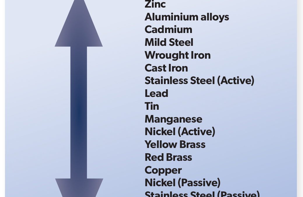
The largest consumption of sacrificial anodes is in the protection of energy related structures in seawater.

• Anode Alloys
Zinc was the initial choice for marine protection systems and is now mainly related to shipping applications. Zinc alloys do not perform well at elevated temperatures, loss of driving potential and formation of adherent corrosion products, with some reports of high consumption rates, means that they are not considered at temperatures much above ambient. Zinc anode alloys have the advantage that their current capacity is unaffected by operating current density and are therefore well suited to applications where an anticorrosion coating is present.

Aluminium alloys, based on the addition of 5% of zinc and 0.15% tin give a desirable driving potential but only very low efficiency unless solution heat treated after casting, when better capacity is achieved. Aluminium with 5% zinc, 0.02% indium and 0.2% silicon, is the commonest in general use and has found application at higher temperatures, driving potentials hold up but at the cost of a significant proportion of current capacity. Aluminium anode alloys experience a reduction in current capacity at reduced operating current density, this being significant at very low current density such as may be found with well-coated pipelines.

There are unlikely to be any fundamental advances in anode alloys in the foreseeable future. The use of zinc in offshore applications has been limited by opposition from environmental lobbies leading to banning of their use, and the issue of anode performance at elevated temperatures still has to be resolved. Testing has shown that anode performance is significantly reduced at elevated temperatures, but virtually all that testing has been under isothermal conditions, with little testing under heat transfer conditions, which is much more likely to be the actual service situation.

Future offshore developments are venturing into environments more aggressive than plain seawater. The particular issues surrounding Lake Maracaibo are well documented, less well known are those of the Black Sea, where the seabed is at a great depth and covered with centuries of organic matter. The suitability of existing materials and engineering practices will need to be confirmed and if necessary, adapted to such applications. Seawater having limited access to oxygen replenishment is another design challenge.

• Production of anodes
Most anodes are produced by casting the alloy onto an insert (usually a steel pipe or frame which supports the anode material and facilitates its attachment to the structure to be protected) in a permanent mould usually made of steel. Care must be taken in the casting process to take account of expansion of moulds and inserts, and contraction of anodes. Anode alloys are formulated for their electrochemical properties rather than their structural ones and this has led to problems of cracking of the anode material particularly with aluminium anodes. It is unlikely that production techniques will change significantly.

• Application engineering
The shape of an anode will contribute markedly to its performance in a cathodic protection system.
Fixed production platforms have a life expectancy of 30+ years and are usually only provided with coatings in the tidal areas. Anodes for these applications are generally up to 30cm in section and up to 300cm in length with a trapezoidal or circular cross section. Inserts are now invariably a tube with ends bent to facilitate attachment some 30 cm from the surface to be protected. Inserts are made from steels with a composition compatible with welding direct to the structure or via a doubler plate. A typical production platform may stand in 200 metres or more of water and have 1000 tonnes of anodes providing protection for the life of the structure. Care must be taken in the design to allow for current drain to assorted attachments, including but not limited to, production risers, export pipelines and piling. Failure to make due allowance for such current drain may compromise the protection system life, or in extreme cases prevent protection being achieved at all.

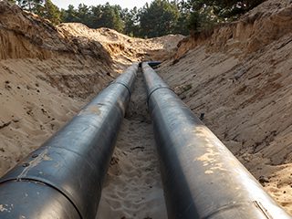
Probably the most interesting application engineering challenge is with anodes for submarine pipelines. These traditionally are segmented or semi cylindrical (half shell) bracelets which are a tight fit to the pipe. A taper may be cast into the leading and trailing edges of the anodes for smaller diameter pipelines. Larger diameter pipes often have a reinforced concrete weight coating several centimetres thick over the anticorrosion coating, and in this case the bracelets are made to a corresponding thickness in order to minimise any ‘step’ in the surface profile causing impact as the pipe passes over the stinger or boom on the lay-barge during laying.

Traditional engineering principles for the cathodic protection of pipelines are therefore a compromise between protection requirements and installation requirements. Future developments are likely to focus on the balance of this compromise in favour of the protection requirements ever recognising that the political, environmental and economic results of getting it wrong are usually disastrous.

• Current density for protection
In almost all cases the cathodic current density to initiate polarisation is substantially greater than that required to maintain it, exceptions being where there is a substantial water velocity past the structure or some other depolarising effect such as frequent storms. Protection system specifications are now recognising this and require an initial polarising current density and (much) lower maintenance current density. This will generate considerable rewards and impact substantially on design philosophy in the future. The selective use of coatings on parts of a fixed structure can lead to reduced anode requirements and greatly assist with the initial polarisation current issue. Any reduction in float-out weight can yield significant cost savings and will be relentlessly pursued although the risks make such progress slow.

The design of protection systems for coated structures requires an estimate of the levels of coating break down over the life of the structure to be made. The CP system is then designed to cater for this. In the future this combination of coatings and cathodic protection will merit increased attention, as even a low-grade coating with a relatively short life would address the initial polarisation current.

Offshore pipelines unlike platforms are almost invariably provided with a very heavy-duty anticorrosion coating, and reinforced concrete weight coatings on top are common. Pipeline coating breakdown levels used in CP design are typically 2.5% over the design life of the line or less. The future may well include superior anticorrosion coatings to those used at present. Cathodic protection designs could therefore have fewer unit anode installations, however distribution of protection along the length of the line will be a serious consideration, and anodes may be installed only at the ends of relatively short lines, or even fewer anodes added after the line has been laid in the case of longer lines.

• Quality control and quality assurance
The importance of effective QC & QA cannot be overstressed. Anode producers use instrumented analytical techniques such as infrared spectrophotometry, spark emission spectroscopy, atomic absorption spectroscopy, and plasma emission spectroscopy, to control alloy chemistry. When undertaken by properly trained technicians with access to traceable standards these methods provide rapid and reliable compositional data.

The use of steels with appropriate certification and welding to coded practices can give suitable assurance in respect of inserts.

The use of electrochemical testing as a quality control procedure has become mandatory on alloys, and a whole industry has grown up around such testing both by producing foundries and independent test houses. The testing procedures now used involve small samples of anode alloy often prepared in such a manner as to remove the entire ‘as cast’ surface. Great store is placed on the absolute values of current capacity per unit weight obtained.

In more than 40 years of practice in the use and manufacture of aluminium alloy sacrificial anodes, the author has never heard of a report of the failure of an anode whose chemical composition was within specified tolerance, to operate as expected. Thousands of electrochemical tests have been undertaken at great expense for no benefit whatsoever. It is to be hoped that the future will see realism and this waste of effort and resource consigned to history.

• System design
The calculation of the weight of anode alloy required to protect a structure is given by a simple calculation using area to be protected, current density, required life, and anode capacity. It is a brave designer that claims to know the true surface area of the structure. Dimensional tolerances of rolled sections of the sizes from which offshore structures are made are known quite accurately but it is surprising what bits get left out of the calculation let alone any correction for surface irregularity. Maintenance current density is variously quoted at figures between 0.140 A/m2 and 0.040 A/m2
for the same location, a factor of almost 4 times.

Anode current capacities for Al-Zn-In alloys are variously quoted between 2550 Ahrs/kg and 2750 Ahrs/kg. In general, the lower figure is on the basis of long term field tests, and the higher figure is on the basis of those short term lab tests mentioned previously.

Future design of sacrificial anode systems should focus on true surface areas and the current density required to polarise them, rather than squeezing the last drop of performance out of the anode alloy, and then justifying it with spurious testing.
Dr Bob Crundwell

Fellow’s Corner – Issue 165

Fellow’s Corner – Issue 165

This series articles is intended to highlight industry wide engineering experiences, practical opinions and guidance, to provide an improved awareness for the wider public, and focused advice to practicing technologists.  The series is prepared by ICorr Fellows who have made significant contributions to the field of corrosion management.  This month’s contributions include, Bijan Kermani on the problems associated with geothermal energy production, Dirk L. van Oostendorp on challenges of dealing with aging infrastructure, and Dr Gareth John on the multi-discipline nature of corrosion engineering.

Materials for geothermal wells

Anthropogenic global warming (environmental pollution originating from human activity) is the central issue of our time. Shifting weather patterns and the associated consequences threaten the biosphere and human civilisation alike. Global concern about this existential threat/risk has initiated a new Energy Transition (ET). The term is not novel, and incorporates many factors. It has previously been driven by technology, economics, environmental considerations and in developing nations’ living standards. In its current guise, it is also determined by politics, government policy and concerted activism.

Energy demand supplied by hydrocarbons will continue to influence geopolitics in the post-coronavirus world. In the coming years, CO2 and greenhouse gas (GHG) policies will bring continuing changes in how energy is produced, transported and consumed. ET is global, but nations will respond to it differently depending on their own particular circumstances. In this transition, geothermal energy can play a significant role as a source of carbon free and sustainable energy. It can potentially provide a continuous, uninterrupted supply of heat or electricity and become a major contributor to the energy mix to meet a current and future growing global demand.

Geothermal Energy

Broadly speaking, geothermal energy is the natural heat present within the earth’s core, mantle and crust. Typically, this can be divided into low and high energy systems (HES). The former includes direct geothermal applications to heat single buildings, as well as whole districts, and HES covers electricity generation. The associated technologies for each system differ and are greatly influenced by pool depth, geographic location as well as regional geology, and governed by temperature and pressure conditions. HES is most prominent in active tectonic zones in many of the regions of the world, and normally requires relatively deep drilling and is the subject of the present overview. 

Use of geothermal energy in HES, generally involves producing and injecting wells. In this, steam/fluid is drawn up in producing wells and eventually enters surface facilities to rotate the turbine and generate electricity.  The returning water is then injected back into the reservoir via
an injecting well for pressure enhancement. The simple cycle is schematically shown in Figure 1. Recent developments have achieved a number of milestones in HES including drilling deeper and tapping into hotter sources potentially offering more energy than standard boreholes. 

The chemical nature of most geothermal fluids poses some severe technical constraints and many challenges in tapping into these resources.  The prevailing conditions include the type of geothermal system, the reservoir depth and the operating conditions.  Amongst the challenges are corrosion, particularly affecting carbon and low alloy steels (CLASs) as the main and cost effective material of choice, and scaling of wells and heat exchangers. While corrosion and scale prevention can be achieved by injecting inhibitors based on quaternary amines into the fluids, their applicability and effectiveness are limited.  Another main challenge is in relation to constraints on capital investment. These underline the significance of materials optimisation to allow for economic systems which are fit-for service. 

This brief overview outlines two elements in relation to geothermal well completion including, (i) types of corrosion threat and, (ii) a summary of suitable tubing materials and their respective optimisation.  It is certainly not exhaustive and only attempts to set the scene for furthering future more focussed studies.

Potential Types of Corrosion Threat in Geothermal Wells

Corrosion challenges in geothermal energy production differ greatly from those of the oil industry and may be somewhat similar to those of steam generation, nuclear or the petrochemical industry.  Nevertheless, due to the absence of pertinent methodologies, those involved with geothermal well construction continue to adopt oil and gas industry corrosion models and materials selection criteria.

Principal types of corrosion threat experienced in HES include:

H2S, CO2 and low pH corrosion or a combination of these in production mode, and,
Primarily O2 corrosion in the injection mode. 

These are to some extent similar to the threats experienced in oil and gas production, such as metal loss or environmental cracking (EC) or a combination thereof. While during production, oxygen may not be present, although it may be involved when using untreated fresh water for drilling, stimulation or in injection mode and subject to well depth.  These corrosion threats are particularly in relation to HES, although they may be equally applicable to low energy systems depending on operating conditions.  

In addition, erosion-corrosion is also a topic of importance particularly where sediments are lifted with the produced fluids. 

The likelihood of corrosion threats for specific well components in the production mode are summarised in Table 1.  As mentioned earlier, in the injection mode, unless injection water contains CO2 or H2S, the main corrosion threat is related to the chemistry of injected fluid and the presence of O2 affecting the integrity of fluid flow wetted parts of the well. Where system corrosively is high (red zones), in injection mode O2 corrosion type may take over. 

Materials Optimisation 

In most high energy geothermal wells (HES), high system corrosivity and low in-situ pH in the production stream renders CLAS unsuitable for fluid flow wetted parts and industry experience of its use has been inconsistent.  A summary of materials options for geothermal wells in production mode is presented in Table 2, taking on board both aspects of metal loss corrosion and EC outlining limitations and suitability.  This is always complemented with a full reference to whole life costing. It is apparent that for the majority of applications CLAS may prove inadequate in terms of metal loss corrosion resistance, and corrosion resistant alloys (CRAs) including Ti alloys can become the obvious options.  In the absence of fluoride species and subject to benign mud acids, Ti alloys in particular have a good track record for such applications.  In addition, glass reinforced epoxy (GRE) tubing has been used for low pressure systems at temperatures not exceeding 90 C offering corrosion resistance. In the case of clad pipe, application specific studies need to be carried out.  

The case of GRE lined tubing is an ongoing subject, although its use for the injection wells is a proven technology particularly in hydrocarbon producing water injection wells subject to meeting operational conditions. However, minimising O2 entry to the wells can allow the use of CLAS for the injection wells.

Other key points in high energy geothermal well design which require consideration include derating of mechanical properties for tubing/casing grades due to elevated temperature exposure and also potential scaling.  However, these are considered beyond the scope of the present article.

While providing an overview, it is apparent that the subject is of great importance and warrants further research in areas of corrosion prediction, materials optimisation and well categorisation to move the sector further forward in offering carbon free and sustainable energy in ET agenda.

Bijan Kermani

Challenges of dealing with aging infrastructures

When we switch on the light at home, it comes on to illuminate the room. When we open the tap, we get water for drinking and cooking. These simple facts are often considered normal in our modern world and taken for granted. However, it is far more complicated than that.

For our electricity, we rely on power generation plants and facilities, and our water is supplied to us through a complex network of purification plants and underground pipelines. The concerning aspect is that the majority of the infrastructure operating quietly in the background is over 40 years old. For most large, cross-country pipelines, they were originally designed for 25 years of service, so we are well beyond that point now, yet still functioning.

Corrosion engineers and specialists are being called upon more frequently to assess the condition of this infrastructure, identify specific areas where remediation is needed, and assist in the process of extending the operating life of these already aged assets. This is a very different role than where corrosion engineers were typically involved in the past, and a different mindset is required when considering an extended timeline.

There have been a fair number of incidents in recent years to remind us of the consequences when aged structures can no longer perform as expected. In-service failures on water transmission and distribution pipelines have demonstrated an increasing trend over the past decade and this represents more of an inconvenience for some people, while it remains unnoticed by the majority of the populace. After all, it is only water, right? Industry statistics indicate that there are approximately 700 water main breaks per day across North America. A study by Utah State University found that break frequency increased by 27% between 2012-2018. Corrosion turns out to be the leading cause of these leaks on cast and ductile iron pipe.

But pipelines are not the only structures that are affected by corrosion, whereby catastrophic failure can occur. The collapse of the Champlain Towers South condominium in Surfside, Florida was a graphic and very visual example. While the investigation is ongoing, it is believed that corrosion on the steel reinforcement was at least a contributing cause.

So how do we properly assess and manage aging assets? For many years, the discussion generally involved the ‘3R’s’ … repair, refurbish, replace. The cost of replacement, coupled with the dependance that has evolved on many of these aged structures, makes replacement very costly and unfeasible. Repair can be a solution for minor damage, or as a short-term measure. This means refurbishment or rehabilitation become the most reasonable approach, meaning we must approach it with different and alternate methodologies.

Over the past decade, there have been tremendous advances made in coatings, composites, and inspection technologies. Using tools like phased-array ultrasonics or pulsed eddy current, technicians are able to look deeper and with more detail into the condition of structures, be it reinforced concrete or pressure vessels. The successful addition of carbon monofibers and Kevlar into composite systems have increased the strength of the final repair, on an antiquated wooden penstock, for example.  New epoxy coating formulations have been developed and tested, these include the addition of performance enhancers, such as sintered ceramics, to increase strength and abrasion resistance. Finally, developments in microelectronics have now added the possibility of installing remote monitoring as part of a refurbishment project that allows for real-time assessment of key parameters, such as corrosion rate, cathodic protection potentials or pH of operating environment. With this data, it is possible to apply predictive analytics and determine not only what is required, but also when the necessary work is best completed. In parallel, corrosion engineers are being asked to assess the economic implications of the repairs through Life-Cycle Cost Analysis, as a means to compare the benefits from various repair alternatives and ‘net present value’ considerations of the subject assets.

The role of a corrosion engineer is changing, as corrosion control becomes a more integral part of the overall asset integrity management process, and training in these “new” disciplines is an important part of a corrosion engineer’s professional development. The addition of non-technical skills, such as engineering economics, are becoming important tools for corrosion engineers.


Dirk L. van Oostendorp,
Director of Engineering, Corrpro Companie
s

The Multi-Discipline Nature of Corrosion Engineering

One of the more interesting aspects I have observed in more than 40 years working in this industry is the frequent requirement to seek input and support from a wide range of scientific / technical disciplines in solving corrosion engineering problems, both large and small.  

Generally, corrosion engineering requires input not only from metallurgists / materials scientists (to some, perhaps, the “traditional” corrosion engineer’s background), but also from chemists, chemical / process engineers, mechanical / structural engineers, microbiologists, mathematicians / statisticians, and others. For the modern corrosion engineer, one’s work
can also cross several technical areas, from desktop consulting through to failure investigations, site inspections and audits, as well as laboratory analysis and testing.  

In my company (and before that CAPCIS Ltd) I have been privileged to have been actively involved in many hundreds of projects over that time, covering a wide range of industries including oil & gas, petrochemicals & chemicals, water & wastewater, power generation, civil infrastructure, transport, with the work ranging from initial design and selection for new facilities, to operational and maintenance issues and through to failure investigations. In my experience, successful project completion (regardless as to the type of activity) involves input and interaction from a range of specialist disciplines. By way of example, as part of my post-doctoral research project for corrosion of steel in concrete (back in the late 1970’s), I noted that it was only after corrosion scientists and concrete technologists started to talk to each other, with respect to how the chemistry within concrete interacted with the reinforcing steel, was any development / understanding of this world-wide problem developed and, from that, successful solutions for both existing and new structures developed.

It is self-evident that the very nature of corrosion requires a knowledge of chemistry, to ensure an understanding of the electrochemical processes at play and the corrosivity of the environment under investigation. But also, whilst chemical knowledge is critical with respect to assessing if conditions exist for corrosion to occur, the way any material reacts to a given environment also affects how corrosion manifests (if at all); hence, a metallurgical / materials engineering knowledge is also required.

The requirement for input from other technical disciplines varies on a case-by-case basis. For example, input may be required from microbiologists to assess the threat of Microbiologically Influenced Corrosion. Advice from production chemists may also be needed, for example, to perform mineral scale precipitation threat assessments, as well as wax and asphaltene modelling / testing.

In many cases chemical / process engineering input is necessary to fully characterise the extent of corrosion threats across a facility, for example, through analysis of heat and mass balance data, and understanding fluid flow behaviour in a system and consequent impact on water hold-up / drop-out and production chemical performance.

Of course, just understanding the likelihood of corrosion and how it manifests itself is only part of the overall problem, the key question is often “is the structure / component / facility, fit-for-service (FFS)?”  This is where mechanical / structural engineering comes in, from simply determining the minimum allowable wall thickness for the item, to determining the limiting conditions for corrosion damage.  For example, determining critical defect size for the operating pressure (or the inverse, the safe working pressure for an existing defect), to critical defect size for crack initiation / propagation and overall fatigue life.

Finally, mathematics in general (and statistics in particular) play a key (if often overlooked) role in day-to-day corrosion engineering.  Many corrosion-prediction models (as well as integrity models) are statistical in nature as they provide an estimation of the corrosion rate / failure condition under different conditions by interpolation and extrapolation of results from laboratory tests and (in some cases) real life data. Data trending to allow extrapolation from current to future conditions is also a major aspect of corrosion engineering.  Fundamental to any such analysis is a need to understand that any model is based on assumptions and/or a limited data set, and hence, having the knowledge to understand when to accept and when to question the results is also vital.

A good example of a multi-faceted project is one we carried out for ADNOC Offshore (then ADMA-OPCO) several years ago in relation to assessing the impact of a proposed CO2 enhanced oil recovery (EOR) project for a mature offshore field [1].  In this case there were significant concerns given the assets were over 40 years old and several subsea flow lines and other facilities would be directly impacted.  At the time there was very little published information relating to expected corrosion in the various operating conditions that would be created by the new CO2 EOR and most predictive models had not been verified for the very high partial pressure of CO2 that would be encountered.

As such, the study covered a wide range of interrelated tasks including:

Process engineering – to assess issues associated with handling super-critical / dense phase CO2, including predicted varying process compositions / production rates for the different field assets / facilities.

Corrosion modelling – to estimate expected corrosion rates for the range of operating conditions covering varying partial pressure of CO2 / H2S, and water content.

Laboratory testing – to confirm corrosion rates for natural (non-inhibited) and inhibited conditions, under super-critical CO2 conditions.

Statistical analysis – to compare the corrosion rates from the modelling work with laboratory test data and hence to provide realistic predicted rates across the facility.

Integrity assessment – based on the condition of the existing assets / facilities and expected future corrosion rates, perform integrity and remaining life assessments.

Corrosion monitoring – identifying what system modifications / additional facilities would be required to ensure adequate on-going corrosion monitoring and assessments.

Field surveys – to assess the existing facilities and have discussions with on-site personnel.

Materials selection – for the new injection and production wells, including use of corrosion resistant alloys for different components. 

Production chemistry – to determine the expected impact of asphaltene formation (due to changes in system pH from CO2 injection) and options for mitigation.

Considering all the different scientific and engineering aspects that need to be taken into account, it is not surprising that a Corrosion Engineer is often considered as a jack-of-all-trades (although I prefer the more poetic term polymath).  However, whilst a broad overall knowledge may be sufficient for routine situations, the above makes it clear (I trust) that for many complex cases it is important that expertise from all the appropriate technical disciplines, and input from different sources, are utilised to ensure that a fully comprehensive and effective solution is developed and applied.

My own background, BSc in Chemistry & Mathematics, followed by a PhD and post-doctoral research at the Corrosion & Protection Centre (University of Manchester) before joining CAPCIS back in 1981, has allowed me to get involved across all the different scientific, technical and engineering areas I have discussed above. I must admit that it is this multi-discipline nature of corrosion, with all the different challenges that it throws up, that makes it such an interesting and intellectually rewarding field to work in. 

(1) H A Binthabet et al Corrosion management challenges related to CO2 enhanced oil recovery on existing production infrastructure, paper no 7649, presented at NACE Corrosion 2016, Vancouver, Mar-2016.

Dr Gareth John, Executive Consultant, Intertek Production & Integrity Assurance.

The problem with black powder deposits

The problem with black powder deposits

The article by Al-Otaibi and Deshmukh (p23 Corrosion Management September/October 2020) provided important insights into how intractable black powder problems can be in hydrocarbon systems. It also reminded Chris Googan of a recent investigation into a black powder problem on a floating production storage and offloading (FPSO) installation. Here’s his anonymised summary of that case…

The Problem

The FPSO operated independently under contract to a major oil producer. In around 2014, a black powder problem became apparent in the gas processing system. The rogue solids periodically blocked strainers at the gas cooler inlets, necessitating shut-down of one of the twin gas processing trains. To avoid flaring the gas, the rate of oil production had to be reduced. Unless the FPSO operator could demonstrate that the black powder problem originated subsea or downhole, its contract required it to carry the costs of unblocking the strainers. It also incurred financial penalties arising from the cut-backs in oil production.

The FPSO Operator’s Investigation

The FPSO operator embarked on an investigation which, unfortunately, lacked both objectivity and any corrosion specialist support. Every time a strainer blocked, samples of the black powder were sent to a commercial laboratory where they underwent comprehensive, and not inexpensive, analysis: wet chemical, infra-red and x-ray spectroscopy and x-ray diffraction (XRD). The FPSO operator’s desire was that the results would identify corrosion of the oil major’s subsea infrastructure, or solids from the reservoir, as the source of the deposits.

In parallel investigations, the FPSO operator also embarked on an intensive, and likewise not inexpensive, campaign of non-destructive testing (NDT) of its own carbon steel pipework and equipment upstream of the strainers. Its ambition was to demonstrate that the topsides gas processing system was not corroding; so the black powder must be originating subsea.

Analytical Results

Chemical Components
Table 1 summarises a typical set of results from some of the many analyses of iron-based deposits collected from the strainers. It also records the presence of other (non-iron) salts found.

If the information in Table 1 were not perplexing enough, drilling down to the crystallographic nature of the compounds, as revealed by XRD, prompted even more head scratching. For example, the sulfate minerals observed included: szomolnokite, melanterite, jarosite and rozenite, which hardly ever appear in the corrosion literature. None is expected to form in anoxic hydrocarbon production environments. It seems most likely that the sulfate deposits were formed by the post-sampling oxidation of iron sulfide corrosion products when exposed to air. This process would be in addition to the known conversion of iron sulphide to iron oxides in the presence of atmospheric oxygen. (It seems that the need to maintain samples under an inert atmosphere was not fully appreciated by all involved). The relative absence of carbonate (siderite) from the majority of samples suggests that the corrosion products were formed when the H2S to CO2 ratio in the gas favoured the formation of sulphide ahead of carbonate.

The whole assessment, however, was complicated by the bewildering multiplicity of other iron-bearing compounds observed in the deposits. These included sulfides: pyrite, mackinawite, pyrrhotite, marcasite and greigite. There were also oxides and oxy-hydroxides: geothite, lepidocrocite, akageneite, wuesite, magnetite and maghemite. Thus, the vast majority of the deposits in the strainers was corrosion product; but the plethora of crystalline forms obscured the corrosion mechanisms; and provided no information at all on where the corrosion had occurred.

In addition to iron corrosion products, small amounts of halite (NaCl) were detected in some; but by no means all, of the debris samples.

Chasing Isotopes

The nucleus of the iron atom has 26 protons; but the number of neutrons combined with these protons can vary considerably. This means that there are 34 known isotopes of iron. Most are exceedingly rare, and of no interest for our purposes. They undergo radioactive decay to daughter isotopes of manganese, chromium or cobalt with half-lives ranging from nanoseconds to millions of years. On the other hand, there are three stable isotopes: 56Fe, 57Fe and 58Fe, with relative abundances of (approximately) 91.75%, 2.12% and 0.28% respectively. Another isotope, 54Fe, has a decay half-life of a mind-boggling 4.4×10²⁰ years; so is stable as far as we are concerned. It makes up the remaining 5.85% of the iron atoms found in nature.

It has been known for some time that there are slight variations in the iron isotope balance for steels, depending on the ores from which they are derived. This prompted the FPSO operator to commission isotope analysis of samples of the debris, and of the process system steelwork. Its expectation was that this would demonstrate that black powder iron did not originate from the gas system steel. The ratios of 56Fe to 54Fe, and 57Fe to 58Fe were measured for nine steel samples and ten debris samples. To cut a long story short: the results were inconclusive. The span of measured isotope ratios observed in the deposits overlapped the span of ratios observed from the steel specimens. Beyond that, no conclusion as to origin could be drawn.

Inspection Results

As with all such exercises, the NDT campaign produced a glut of data, Unfortunately, however, there had never been a base-line wall thickness survey of the as-built pipework. The best that could be concluded, therefore, was that there had only been “marginal” metal loss compared with the nominal values. The FPSO operator interpreted this as supporting its case.

The Corrosion Assessment

After three years of heroic analytical endeavour, the FPSO operator decided it was time to involve a corrosion specialist in the investigation of this corrosion problem. I was commissioned to review the voluminous data and come up with a report that determined whether the operator or the oil major held the responsibility for the black powder problem.

My analysis took a lot less time than my client expected. Instead of delving into the minutiae of what was in the black powder, I focussed on what was not there. The missing ingredient was the salt (halite).

If, as hoped by the operator, the black powder originated subsea, then the only mechanism for it to have entered the gas production system was in aerosol droplets of produced water carried over with the gas from the slug catcher or gas-oil separators. Any such droplets would have to possess a much greater salt content than iron compound content. Incoming produced water analyses showed typical values of 13 000 mg/l chloride, less than 130 mg/l in total of suspended solids, and less than 1 mg/l of soluble iron. Thus, any droplets carried over would have had to contain hundreds, more likely thousands, of times as much halite as iron. Although there was evidence of isolated instances of produced water carry-over, analysis of the solids, and of the water separated from the gas system, simply failed to find anything like enough chloride to tie the iron to a subsea source.

The remaining plank of the FPSO operator’s case, namely that its gas piping was exhibiting only “marginal” corrosion was also soon jettisoned. Elementary calculations, based on the surface area of upstream off-gas pipe wall exposed, showed that even very low corrosion rates, well below those predicted by CO2 corrosion rate algorithms, would result in ample iron-based corrosion product to account for the observed quantities of black powder.

Lessons Learned

Numerous lessons emerged from this exercise. Some related to the original corrosion engineering of the FPSO’s gas processing facilities. For example, hindsight prompted reconsideration of the original design decision to omit the option of being able to inject vapour phase corrosion inhibitors into the system. It also forced a re-sizing and re-design of the strainers.

From the corrosion perspective, however, I offer two learnings. The first, unsurprisingly, is that it is a good idea to involve a corrosion specialist from the beginning of a corrosion investigation. The second, and perhaps more difficult to ensure, is always to keep an open mind when embarking on a corrosion failure analysis. Conducting the exercise with a pre-disposition to an intended outcome invites the risk of a biased and confused investigation.

Chris Googan, antiCORR

Fellows Corner

Fellows Corner

Material Integrity Assessment of Onshore Assets

Onshore oil and gas assets are vast and usually cover a large area. These can refer to all upstream facilities i.e.  facilities used for production and stabilisation of crude, or downstream facilities i.e., refining facilities. Upstream facilities can be divided into off-plot facilities e.g., wellheads, wellhead piping, flowlines, remote manifolds, trunklines/pipelines,
and on-plot facilities e.g., stabilisation systems, separation/dehydrations systems, flare systems, produced water systems, utilities systems,
storage facilities etc.

Typically, these assets are designed for a minimum of 25 years but in the real sense they are used for a longer period i.e., until total reservoir depletion or a halt in production due to global oil and gas economics. Thus, these assets need to be maintained consistently and occasionally optimised to aid production.

A Materials Integrity Assessment (MIA) is a multi-disciplinary review of materials and integrity of an operational asset with a view to mitigate failure or optimise production. This short article outlines the process for undertaking a MIA of an upstream facility.

A MIA can either be proactive or reactive in nature. These objectives are broadly categorised into the following:

  1. To assess suitability of materials when a proposed brown field modification will introduce new production fluids/operating parameters to an existing facility.
  2. To assess the material/integrity threats due to a change in the current operating conditions that can lead to a failure or loss of containment e.g., unexpected reservoir souring, sand production, oxygen ingress, build-up of microbial activity etc.
  3. To proactively ensure the assets are operating within defined limits.
  4. To proactively apply learnings from other facilities and global best practice.

The scope of an assessment can be the whole upstream facilities. or sections of the facility. This needs to be determined by the Client with the above objectives in mind. The scope will determine the duration of the project (from weeks to months) and the number of disciplines involved e.g., where only an on-plot scope is envisaged, there will be no requirement for a pipeline integrity engineer etc.

MIA Methodology

The methodology, and steps of the assessment are shown in figure1 below:

The scope/objective is defined by the Client in conjunction with the MIA Lead. The corresponding disciplines are defined, and personnel nominated.  It is advisable to have a core team and an ad-hoc team on an on-call basis, a typical team comprises the disciplines shown below:

The ICP (Independent Competent Person) should be an experienced professional with no interest in the asset/facility who will be responsible to vet the assessment and to provide guidance where required. Individual and group roles and responsibilities are then defined with the expected time frame by the MIA Lead. It is critical to note the assumptions and exclusions at this stage of the project.  Where there are known integrity concerns, these needs to be highlighted on a draft heat map displayed on a base PFS/PEFS drawings.  The heat map tends to zero in on the areas that need special attention especially when undertaking a review of a very big asset. It also easily shows areas with similar integrity issues or failure patterns that will help with the assessment. 

Data gathering and review is the most critical phase of a MIA.  The data to be reviewed includes. but not limited to, the Facility Design Basis, Plant Operating Manual, Material Selection Reports, Corrosion Management Manuals, Inspection/Monitoring Data, CP Monitoring Data, Failure/Leak registers, Maintenance Plans/Reports, Trending Reservoir Data etc. Some well-organised and maintained facilities/assets will have this information readily available while others may have insufficient information.

Where the available data is insufficient, then several assumptions will need to be made. As an example, in a particular project where there was no baseline inspection data or any subsequent data after seven years of operation, the integrity assessment was then based on a greenfield (new) corrosion modelling. After going through the material selection process, this was then compared with what was physically on the ground and an evaluation made as to whether the right material selection had been made, and the expected remaining design life based on the existing process parameters. This comparison formed the basis of the subsequent recommendations.

A site/field visit is essential as it gives the team the opportunity to visually inspect piping, flowlines and equipment. It also serves as a verification process of the data provided or any of the identified integrity issues.
The visit should also include interviews with key operation and inspection personnel who will be able to give their observations of any changes in the field and more clarity on the plant operations. Pre-prepared questionnaires are recommended for these interviews.

Interdisciplinary Peer Review Workshop

After the site/field visit, the team write up their findings based on the areas of responsibility allotted to each person. The whole write up is then discussed as a team to fine tune and align the findings. On completion of the interdisciplinary review, it is sent to the ICP who will then have a peer review with the whole team. This serves as a form of technical challenge
of the whole exercise and the conclusions/ recommendations.

The report presentation should include a high-level summary using the traffic light system showing the overall status of the asset with the corresponding updated heat map. This high-level summary is based on a more detailed report of the individual areas. This report needs to include a full explanation i.e., scope/objective, overview/history of the asset, findings, where possible photographic evidence and recommendations. This should also be presented visually in a table. An example is shown (top of page 21) based on the earlier heat map.

Recommendations/Conclusions

The recommendations should list out action points to be carried out by the Client in order to verify the integrity of the onshore asset.  These recommendations generally fall into the two categories outlined below:

Short term (less than 6 months) – These require urgent remedial actions/mitigation to avoid loss of containment of hydrocarbon inventory.

Long term (more than 6 months) – These require non urgent remedial actions to be undertaken over a course of time. Advisably between 6 months to 3 years depending on operational constraints.

The completion of the MIA is the presentation of the report (including a power point) to the Client.  Any grey areas need to be clarified to the Client so the recommendations can be addressed within the given time frame.

A Corrosion Management Program (CMP) manual will include the process design and operating conditions, basis of materials selection, corrosion mitigation, inspection strategy as well as corrosion monitoring methodology. The manual needs also to include the risk assessment of critical assets to determine risk severity, monitoring techniques to ensure that the assets can be operated in a safe and reliable manner and the appropriate inspection methods to manage identified risks to maintain the integrity of the critical upstream surface facilities assets. It should also highlight the critical integrity operating window (IOW) parameters and IOW limits to be maintained during service. An IOW programme, its importance, and how to establish
IOW to enhance asset integrity is discussed in detail in reference 2. 
The CMP manual needs to be revised at regular intervals to highlight recent inspection results, risk assessment data as well as changes in process conditions and additional monitoring requirements.

Corrosion monitoring as documented in a CMP manual can be conducted using a number of direct and indirect monitoring techniques, and the merits and limitations of each monitoring technique need to be considered. For effective corrosion monitoring multiple monitoring strategies need to be used and the collected data needs to be analysed along with appropriate process data.  Details of various corrosion monitoring techniques for field applications can be found in the recently revised NACE publication (3). Installing coupons and corrosion monitoring probes can be useful tools for internal corrosion monitoring.  These are considered intrusive monitoring types as they are exposed to pipeline interiors through appropriate access fittings. Proper safety precautions, following the work permit procedures, along with the deployment of suitably trained personnel are necessary for safe removal and installation of coupons from the pipelines during service.  The NACE document “Preparation, Installation, Analysis and Interpretation of coupon data in oil field operations” serves as a useful guideline (4). Corrosion coupons are usually removed at 60-90 day intervals in order to establish long term corrosion rate trends, while the probes are useful to monitor the corrosion rates in real time. Suitable display of the probe’s output in the facility control room will enable the continuous monitoring of corrosion rates, and to alert the operating personnel in the event of higher corrosion rates in order for the required corrective action to be taken. Both wired and wireless configurations are available. The economics need to be taken into account before selecting suitable corrosion monitoring solutions. For pipelines requiring corrosion inhibitor injection, it is essential to have the probes/coupons installed upstream and downstream of the corrosion inhibitor injection point to monitor the performance of corrosion inhibitors. For reliable field corrosion data, it is essential to install the coupons at locations where corrosion is occurring, or most likely to occur, such as high velocity zones, water accumulation spots, etc. Careful location selection is vital since installing the monitoring devices at incorrect locations could obscure the data obtained and its analysis. Linear polarisation probes and electrical resistance probes are used for routine field corrosion intrusive monitoring of the process piping. Linear polarisation probes are commonly used in water systems, while electrical resistance probes can be used in higher resistivity environments. Formation of scales such as sulphide scale, sand erosion, oily/wax deposits at the sensor elements, can affect the accuracy of collected data. As a result, the collected data needs to be analysed carefully to establish a reliable base line reference for meaningful intrusive internal corrosion monitoring data.

In case of nonintrusive monitoring, probes such as thickness measuring sensors using ultrasonic principles can be installed at plant piping exteriors where continuous piping wall thickness monitoring due to corrosion/erosion is warranted, and a number of such systems are commercially available. These sensors can be installed at multiple locations and the wall thickness data, sensor battery life, and the temperature data, can be communicated in real time to the operating facility control room. The main advantage of nonintrusive monitoring is that the monitoring can be conducted when the plant is in service. In addition, critical piping at higher operating temperatures, and at elevated and inaccessible locations can be monitored.  This approach offers cost-savings by eliminating the scaffolding requirements especially for elevated plant piping sections as well as avoiding the costs associated with the operating facility downtime to conduct the conventional thickness monitoring which would otherwise be required. By analysing the collected data, proactive corrective measures to mitigate piping corrosion along with scheduling the piping replacement in advance with the maintenance and operations team can be carried out. This approach enables the monitoring of the critical piping wall thickness condition to prevent the loss of containment due to internal corrosion thus facilitating the operation of the plant assets with highest safety and integrity, as well as to minimise HSE related events. As well as ultrasonic sensors, other methods such as eddy current testing, electromagnetic field mapping and battery free ultrasonic sensors are also considered nonintrusive monitoring types.

To manage critical upstream assets, microbiologically induced corrosion (MIC) also needs to be monitored and managed whenever applicable. Periodic process water sampling to monitor the planktonic bacterial counts, dissolved oxygen content, biocide residuals can be carried out. In oil and gas systems bio-film monitoring probes, samples from removed pipe sections, debris collected during pipelines scraping to monitor the sessile bacteria present in the system along with water quality parameters, provide good information (5).  A number of test kits are commercially available to quickly monitor the biocide residual in the field and to initiate the required corrective actions. It is equally important to document the results and the implemented corrective actions to establish sound historical records.

To mitigate external corrosion threats, parameters such as periodic cathodic protection (CP) potential, current flowing in the structure, CP rectifier potential/current output levels, anode bed condition of underground assets, need to be monitored and managed within acceptable limits. Most of the underground carbon steel piping systems are usually protected by suitable protective coating systems supplemented by properly designed cathodic protection systems. Periodic visual monitoring needs to be carried out at excavated sections of pipelines to inspect the coating condition and to mitigate any external corrosion threats, and the monitored data along with inspection results should be documented.

When selecting the optimum corrosion monitoring solution from the wide range of available options for external and internal corrosion monitoring, the engineering and operational requirements and monitoring objectives, need to be considered, and thus by implementing a robust corrosion monitoring system combined with an effective data analysis, inspection and maintenance strategy, timely remedial measures, the critical upstream oil/gas assets’ integrity can
be managed in an efficient and sustainable manner.

Dr. H.S. Srinivasan, Saudi Aramco

References:

(1) API RP 571-2020 Damage Mechanisms Affecting the Fixed Equipment in the Refining Industry.

(2) API RP 584-2014 Integrity Operating Windows.

(3) NACE TR3T199-2020 Techniques for Monitoring and Measuring Corrosion and Related Parameters in Field Applications,
Houston, TX.

(4) NACE SP0775-2018 Preparation, Installation, Analysis and Interpretation of Corrosion Coupons in Oil field Operations, Houston TX.

(5) TM0194-2014-SG, Field Monitoring of Bacterial Growth in Oil and Gas Systems.

Galvanic Corrosion – the importance of designing-out corrosion hotspot

Galvanic Corrosion – the importance of designing-out corrosion hotspot

Protecting metallic structures from corrosive attack is not just about using coatings or cathodic protection, the design of the structure also plays an important part.  There maybe situations which call for two different metals, or alloys, to be joined. If these metals are electrically connected under conditions permitting the formation of a “corrosion battery”, then in this situation, one metal can corrode preferentially in relation to the other metal to which it is physically and electrically connected. This is termed “galvanic corrosion”.

Galvanic corrosion is an extremely important corrosion process, and one that is frequently encountered. The principles of galvanic corrosion are used to advantage in the cathodic protection of surfaces by using sacrificial metal anodes or inorganic protective coatings.  The Galvanic Series lists the activity of metals in order, from the most active (magnesium) to the least active (platinum).  When two metals are connected, the metal located higher up the scale will corrode preferentially, and thereby protect the metal lower down the scale from corrosion attack.  As an example, if copper and zinc are connected together, the zinc will dissolve, or be corroded preferentially, thus protecting the copper. The metal attacked is defined as the anode, thus the zinc will serve as an anodic area, and the copper will form the cathodic, or the protected area. The function of each will be identical to that found in the typical corrosion cell, as in the set up for rusting of iron. The intensity with which the two metals react in this preferential manner can be measured by the distance between the two metals in the Galvanic Scale.  As magnesium is at the top of the scale it will have a tendency to corrode in preference to any other metal shown on the Galvanic Scale, conversely, platinum, which is extremely inert, never corrodes preferentially. While the tendency to corrode depends on the kinds of metal coupled together, the rate at which the corroding anode is attacked depends on the relative area of the anodes and cathodes joined together.

If a small magnesium anode is coupled to a large area of steel (as in protection of a ship’s hull), the anode area (being small as compared to the cathode area) will corrode very rapidly. This is due to the entire galvanic current being concentrated on a small area of active metal.  Conversely, if the cathode area is small compared to the anode area the corrosion of the anode will be relatively slow, since the demand on the anode is spread evenly across the whole surface of the metal. It must be kept in mind that the areas of each metal involved are those in electrical contact and not just the areas of metal in physical contact. The area of metals in electrical contact will be determined by those areas which are in contact with an external conductive circuit (electrolyte).

For example, in the use of rivets of one metal to fasten together plates of different metal, we find an excellent example of possible effects of galvanic corrosion. If steel plates (anodes) were joined with copper rivets (cathodes) only a very slow corrosion of steel would occur, since the galvanic corrosive effect is spread out over a large area of steel. On the other hand, if copper plates (cathodes) were joined with steel rivets (anodes), a rapid rusting of the rivets would occur. The small area of rivets would be attacked by all the galvanic current generated by large copper plates and would corrode rapidly.

James McLaurin, Altrad Services

External corrosion of buried metallic static structures (piping, pipeline, tanks, and vessels)

External corrosion of buried metallic static structures (piping, pipeline, tanks, and vessels)

Buried metallic structures are common in the oil and gas, petrochemical, and chemical industries. These structures are exposed to a corrosive underground environment which results in their degradation and eventual failure in the form of loss of primary containment. The preferred fabrication materials for the construction of buried assets are carbon and low-alloy steels. Carbon and low alloy steels with some means of mitigation have low capital and operating cost (Opex and Capex) over the asset life cycle when compared to other engineering materials (e.g., polymeric and corrosion resistant alloys). Other notable reasons are, better environment management, safety and security concerns, and long-term strategic objectives. Whilst most buried assets are made of carbon and low-alloy steels with some means of external corrosion control (e.g., protective coating and cathodic protection system), in specific cases where historic data indicate severe corrosion that cannot be acceptably reduced with some means of mitigation in the exposed environment, the other option is to utilise stainless steel or other corrosion resistant alloys (CRA) to reduce corrosion to as low as reasonably practicable. Despite of the superiority of stainless steel to carbon steel in terms of its resistance to corrosion and environmental assisted cracking, it is not immune to localised corrosion damage in the form of pitting, crevice corrosion, stress corrosion cracking (SCC) and intergranular corrosion. Hence, when CRAs are used, there is a need for monitoring, mitigation and management to achieve asset design life during its operation.

Buried metallic assets are exposed to soil, atmospheric gases, ground water and corrosion activating bacteria such as sulphate reducing bacteria (SRB), and others. External corrosion of buried assets is directly influenced by oxygen as it promotes the cathodic reaction, other parameters that accelerate external corrosion are, soil type (e.g., clay, marshy etc.), pH, presence of chlorides, stray current, and induced alternating current. Stray currents can be direct current from a cathodic protection system (CP) or alternating current, e.g., from powered transit systems, electrical welding operations, and mining operations. Also, buried metallic structures that are less than 500 m from power lines rated at 312kV and above, are at risk from induced ac corrosion, plus pose an induced ac hazard to maintenance personnel, and an adverse effect on the cathodic protection system. Although, industry statistics for buried metallic structure show that failures due to induced ac are rare, best engineering practice and codes (e.g., NACE SP 0169, 2013; NACE SP0285, 2011 and API RP 1632, 1996) recommend effective mitigation based on powerline rating, separation distance. angle of overhead, soil resistivity, coating conductance, type of powerline support pole (e.g., metal/wood etc.), and other factors. It is best to carry out computer modelling to assess the effect of ac interference on a buried structure prior to implementing mitigation measures. Due to the complex variables that influence corrosion of buried metallic structures, atmospheric, soil, microbiological influenced corrosion (MIC), and stress corrosion cracking (SCC) are all possible.

The corrosion rates in different soil types vary with soil chemistry, mineralogy and permeability. Soils with poor drainage like clay are more corrosive than soils with excellent drainage like sand. Soil contains base and acid forming elements. Base forming metals that influence corrosion are sodium, calcium, potassium, and magnesium. Acid formers are chloride, carbonate, nitrate, sulphate and bicarbonate. Chloride ion concentration in water can be determined using the ASTM D 512-12 method (withdrawn 2021) and sulphate ion concentration in water is determined using ASTM D516-16 (2016).

The electrical resistivity of the soil greatly influences corrosion, as resistivity increases, the conductivity decreases, and vice versa. Soil resistivity less than 1000 ohm-cm is severely corrosive, and resistivity greater than 10,000 ohm-cm is considered progressively less corrosive. The ASTM G 57-20 (2020), method is recommended, using the
Four-Pin method or the Soil Box (Nelson meter), for determination of soil resistivity, and for greater depths, the Geonic EM 37 can be used.

Soil pH influences soil corrosivity. At a pH value less than 4, the soil is extremely corrosive to carbon steel and at a value greater than 10 soil corrosion is controlled except in the presence of strong alkaline solutions. Field operating data for carbon steel, indicates it is unaffected by pH except at a value less than 4, or greater than 10, with the cathodic reaction driven by oxygen reduction. As the moisture content reduces, even at higher soluble ion concentration (very dry soil), the soil corrosivity reduces.

At the pH range found in most soil, oxygen would usually be present for corrosion to take place. This is because most soils have either a neutral or slightly alkaline pH which does not accelerate corrosion except when there is poor aeration or differences in oxygen concentration in the soil creating an anaerobic condition that promotes galvanic (differential concentration) corrosion cells.

Sulphate reducing bacteria (desulfovibrio desulfuricans) can be found in soil with anerobic conditions containing organic matter like clay soil. This results in MIC of metallic structures. Details on the characteristics of soil can be found in ASTM STP 1013. For a better understanding of soil corrosion behaviour, it is advisable to collect soil samples at the installation depth for a detailed soil analysis prior to installation of asset.

The predominant damage modes for buried metallic structures are progressively, wall thinning, pitting and cracking. Common failure modes are pin hole leak, small to moderate leak, large leak, rupture and fracture. Because of the adverse effect on people, environment, asset, and company reputation in the event of loss of primary containment, the integrity of buried assets should be considered a priority.

To ensure effective mitigation of external corrosion, during backfill the soil should be carefully selected to ensure it is dry and free from gravel, clay, rocks, marshy soil, and other harmful corrosion activating materials. The buried structure should be coated with a protective coating (often high build epoxy, vinyl ester etc.) and inspected at hold points to ensure conformance to specification. The coating should have high dielectric strength, superior resistance to water ingress, good mechanical properties (adhesion and abrasion resistance), good flexibility, compatible with CP, withstand degradation due bacteria, excellent performance, long service life, and ideally have low application cost. The asset should also be protected with impressed current CP or sacrificial anode CP with a design life greater than that of the structure.

A CP interference survey should also be conducted to rule out stray current, and if found, should be mitigated to prevent sudden loss of containment.  Company standards and codes should be enforced during the engineering, procurement, construction, installation, pre-commissioning and commissioning phases of any buried metallic asset. Because of the criticality of buried assets, it is vital to develop and implement an integrity management programme that is risk-based (API 580, 2016). For pipelines, a risk-based assessment (RBA) should be conducted to determine the remaining asset life. Finally, I would advise the use of ISO 55000 (2014) and 9001 (2015) to develop the asset management plan to increase top leadership commitment to integrity whilst ensuring continual improvement.
Joseph Itodo Emmanuel, Consultant, Joiegloe Global Synergy