In October the branch hosted a 2-part Non-Intrusive inspection (NII) webinar. The two speakers skilfully interweaved their presentations to explain the background to recent NII adoption, and the practical aspects of the new HOIS, for the benefit of a large corrosion engineer audience.
Dr Susan Osbeck, Principal Consultant of ESR Technology started the proceedings off with a talk entitled ‘The Updated HOIS Recommended Practice for Non-Intrusive inspection”.
The inspection of pressure vessels is traditionally done by internal visual inspection (IVI) with human entry that is both risky, and disruptive to production. IVI is required to be carried out during shutdown after isolation and cleaning of equipment, and is both a costly and hazardous activity with considerable production losses incurred during this period. By contrast for NII, the assessment and inspection are carried out externally using advanced automated NDT techniques with the vessel remaining in operation.
HOIS (Harwell Offshore Inspection Service) is a very well established (>30 years) joint industry project covering all aspects of good practice for Non-Destructive Testing (NDT) in the oil and gas industry. NII is a process not a technique, and HOIS have developed a framework to improve industry confidence in it. These inspection design concepts started in high value projects in the nuclear industry and were then taken up by Oil Industry operators, particularly in the North Sea. HOIS Guidelines were originally published as DNV-RP-G103 and over the years the practice has spread worldwide throughout the Oil & Gas industry.

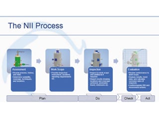
The NII Process – Dr Susan Osbeck.
The NII process is essentially a 4-step process.
1. Firstly, in the assessment phase the vessels’ history, process, and risks, are reviewed to determine the suitability of techniques.
2. A work scope is then developed with respect to instructions, locations and reporting requirements.
3. The inspection phase is then carried out to fully meet all requirements.
4. Finally, the process of evaluation is carried out and any repair recommendations made.
A thorough screening process is first undertaken to assess whether a vessel is suitable for NII. Once agreed, it is assessed as to whether degradation of vessel wall is expected to occur on an A, B or C type level of severity (see later for explanation of these levels), and if it can be safely predicted. Calculations can then be made of the required NII coverage for A, B or C graded vessels, and the probability of detection of any metallurgical flaws of given depth/aspect ratio. There is also consideration given to the homogeneity of any expected flaw distribution.
For the scope and inspection, the HOIS practice has recommended techniques in the form of simplified tables which relate to the vessel shape, cladding, weld types, and nozzles and flanges. The evaluation phase later looks at whether the inspection has met the requirements that were set out, i.e. was the right coverage and targeted locations achieved, were the correct scanning techniques utilised and the overall probability of detection assessed.
The latest revision was published as HOIS-RP-103 in 2020, and updates, and the new features mentioned here, can be found at: https://www.esrtechnology.com/index.php/32-news/news-articles/423-updates-to-recommended-practice-for-non-intrusive-inspection-hois-rp-103
This excellent introduction to the NII Process was followed by further insights from Neil Wilson, Principal Corrosion Engineer ENGTEQ, who discussed ‘A Corrosion Engineer’s Perspective’.
The presentation focused on detailing the physical aspects of NII which are most relevant to corrosion engineers, for example, in predicting where damage may occur and the evaluation of results. It was stressed that all NII requires buy-in at senior management level in terms of acceptance of alternative NII procedures (not every item of equipment being suitable). On the plus side there may be considerable cost savings due to increased production time (less inspection down time). Corrosion engineers are very central to the NII process in the preparation of the assessment, the work-scope, the evaluation of documented results, and in using the data obtained to drive future inspection programmes.
Neil emphasised that NII is certainly not a substitute for RBI (Risk Based Inspection) approaches and it is only one component of the overall RBI assessment process.
The performance of an NII assessment Inspection was fully explained:
1. Strategy Type A, where no degradation is expected; this usually applies to Corrosion Resistant Alloy (CRA) vessels, commonly of stainless steels and Carbon steels (CS) with low degradation rates, such as vessels in dry gas service, with good service history and high confidence of no upsets that would cause internal corrosion. It also applies to CS vessels which are internally clad with a layer of CRA. Typically, one would inspect 5-10% of the vessel looking to confirm absence of degradation at all locations throughout the vessel. There is usually high focus on nozzles and ports, with a larger percentage selected and all types covered. A study of a CS vessel with hot rolled CRA bonded cladding was described, for which the data showed the results for wall thickness only, and confirmed that the cladding interface was is intact with no wall loss breach or disbondment.
2. The study then moved on to a Type A+ vessel with an internal weld overlay cladding around the nozzle which had multiple overlay welds (MOW) with a much coarser grain structure and an uneven surface determined by the weld beads. This type of structure normally causes scatter of NDT beam detection methods and it is thought impossible to detect stress corrosion cracking (SCC), or fine pitting in MOW, so how can this be assessed? The focus in this NII situation would be at the interface of cladding, and CS corrosion would be evident at the CS interface, (if present) following failure of the CRA cladding.
3. For Type B Vessel inspection, the likelihood of defects being present is often much higher, so inspection coverage is closer to 25%. The entire vessel floor would be included along with most nozzles.
4. For inspection of Type C, such as polymer coated CS, significant degradation would be expected with medium to high progression and the locations not easily predicted. Coating breakdown is often random in distribution and even with 50% of areas inspected and no flaws detected, there is still little confidence that there are no flaws, so often 100% NDT inspection is necessary. For NII it is necessary here to inspect fully for wall thickness loss, as coating condition cannot be seen or verified accurately. Such an inspection is significantly more costly of course.
NII is really for internal condition assessment only, external corrosion and issues such as corrosion under insulation (CUI) remain difficult and are assessed by other accepted procedures/technologies.
For the final stage of the process, the results must be checked against the requested work scope, e.g. are the NII findings as predicted for the category of vessel inspection? Are there new previously unidentified damage mechanisms additional to previously identified and are there others that don’t seem to be currently active?
The vast majority of NII inspection results are quantitative and these allow accurate prediction of remaining vessel life. The results also increase confidence in the prediction of degradation types and locations for future inspections, and provide useful information about density and homogeneity of corrosion. These items are typically not well covered by traditional intrusive type inspection and manual NDT, therefore this is a major advantage of using NII.

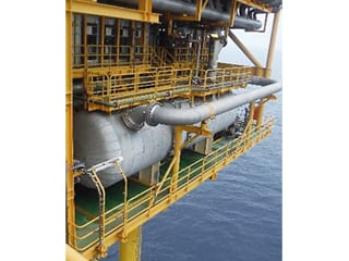
NII Inspection Strategies for Offshore Vessels – Neil Wilson ENGTEQ.
The branch held its annual joint event with IOM3/MIS (The Mining Institute of Scotland) on Tuesday 24th November 2020.
This webinar presentation was specifically designed to make members of the audience think outside the box in terms of approaches to materials selection, and how the research work of the defence and emergency services can be utilised in protection of personnel employed in the Energy Industries.
Professor Debra Carr (CEng FIMMM FCSFS CF), Defence and Security Accelerator, gave a fascinating presentation on body armour called “Saving their Skin (and other organs): Military and Police Personal Armour”. The talk focused on personal armour such as is worn by police and military personnel, the design of the garments, the specialist materials employed, and how they work to afford protection.
Protective armour can be in the form of simple tabard style waistcoats with helmets, eye protection or visors. Other types of armour such as body suits, ballistic blankets and shields are used for control of public order or ordinance disposal. The main purpose is to save lives and prevent or minimise life changing injuries.
Body map injury pattern summaries from conflicts during the last century have shown that there is a greater threat of injury to military personnel from scattering fragments than there is from direct ballistic hits such as bullets.So secondary fragments are more likely to kill or incapacitate personnel than direct impact from bullets, making general body armour covering more important than say just head or torso protection. This is borne out by surface wound mapping which demonstrates that injuries are spread generally across torso, limbs and head, rather than target the central torso or head.
Wound ballistic studies have been extensively studied using high speed video to capture images of ball bearings fired through blocks of translucent gelatine, which is a good model for human and swine tissue, and visual patterns show creation and subsequent collapse of cavities, replicating the wider damage during the passage of a bullet. The damage patterns were reproduced using prepared swine and deer carcasses to show realistic tissue damage expected in humans.
Some of the greatest threats these days to police appear to come from sharp weapons such as knives and concealed blades, low velocity pistols and shotguns. Common kitchen knives are often ‘weapons of choice’ of urban conflict. Studies of knife use and attacker behaviour are used to identify critical areas required for protection of officers. However, essential areas of coverage have to be balanced with the ability of personnel to do their job and avoid restriction of movement. PPE (Personal Protective Equipment) such as jacket and helmet design have to be arrived at through balance of these criteria.
Typical types of materials used in jackets:
1. High strength woven fabrics which are either para-aramids such as Kevlar® or UHMWPE (Ultra High Molecular Weight Polyethylene) such as Dyneema® or Spectra®, like those used in high stiffness ropes. Multiple layers of these fabrics are used to provide increasing amounts of protection, but a typical Police vest only weighs about 2 kg.
2. Sharp object protection armour which still uses old fashioned chainmail or resin coated fabrics, (the key to prevention of knife penetration is to change the kinetic energy density during an impact event by blunting the tip or capturing tip within the mail).
3. To stop penetration of fragments and pistol bullets, the specialist fabric also works by dissipating impact energy along yarns during fibre failure. Pyramidal patterns occur in the fabric due to vertical and horizontal lattice alignment of fabric. The high effectiveness of the police body armour was demonstrated by the mushrooming of 9mm pistol bullets on impact.
4. For threats such as high velocity rifle bullets, ceramic based composite backed plates are used on top of the general armour. The ceramic plates are typically alumina or silicon carbide which are up to five times the hardness of steel and bonded with composite fabric on the rear. The ceramic is impacted but being much harder, the bullet deforms and may fracture itself and its trajectory hindered. It leads to a conical deformation of the ceramic and a buckling of the adhesive and fabric backing without failure.
Professor Debra Carr went on to describe ‘Behind Armour Blunt Trauma’ (BABT), which is a non-penetrating injury resulting from armour covering the body. The bullet does not penetrate the armour but there may be minor breathlessness, bruising or occasional rib fracture.
The main challenges for the future maybe in the types and thicknesses of materials used in armour, as the key objectives are to reduce bulk and mass, whilst preserving the protection level. It is also essential to prevent restriction of movement of the wearer while increasing coverage and improving breathability, cooling and ventilation.

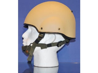
Protective Helmet Design – Professor Debra Carr.
For Oil and Gas drilling and other Energy / Mining applications, there are many potential applications of these corrosion free and advanced materials.
Blast test curtains supplied from US companies, are commonly used Offshore, but Professor Carr and her team are now assisting UK companies with specific Oil and Gas protection problems, and would welcome any enquiries at: djcarr@dasa.service.mod.uk
The branch sponsorship level continues to grow despite challenging times. Branch sponsors have remained extremely loyal and appreciative of the large number of technical events being provided. There are presently 17 confirmed sponsors for 2020-2021 session. Joining us this year are: Axcess Corrosion (US), IMRANDD Consultants, NCIMB (Laboratories) Ltd, Oil and Gas Corrosion Ltd.
The latest information about Aberdeen events can be found on the diary page of this magazine, and at; https://www.linkedin.com/in/aberdeen-icorr/, and all Aberdeen events are recorded and may be found at; https://sites.google.com/site/icorrabz/
